on the board itself. The board takes in dual AC input. JHL Class A headphone amplifier pre-amp assembled board - $38.80 : Enjoy in your hi-fi project, diy tube amp, amplifier diy, amp diy
OK, that means you take 4 wires to the PCB.
These must be kept as 2wire pairs.
One pair from one secondary to one set of AC terminals and the second pair from the other secondary to the second set of AC terminals.
Better if the two wires are a twisted pair with the smallest loop area at the two ends to minimise interference.
BUT !!!!
I can only see three power terminals. That means it is not a dual AC. It is a centre tapped that you need.
You can convert your dual secondary to centre tapped.
Find and connect the correct phase of the two secondaries. Power on the transformer via a Mains Bulb Tester. Measure Vac from one secondary to junction. Measure from other secondary to junction . Measure across the two secondary wires. This final measurement should be the SUM of the two junction measurements. If this final measurement os near zero Vac, then one of the secondaries is inverted phase. You need to swap ONE secondary pair to remake that junction. Measure across the two secondaries again. Does it mow measure double voltage?
Take one wire from that junction and the two other wires as a twisted triplet to the three power terminsls at the edge of the PCB.
Keep the loop areas at the ends as small as possible to minimise interference.
Last edited:
Andrew here's a closeup of the board
An externally hosted image should be here but it was not working when we last tested it.
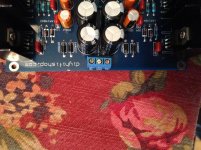
Yes, the 4 off 1n4007 form the bridge rectifier.
The three terminals marked AC GND AC are for the three transformer wires. AC Centre Tap AC.
You can bring the CT as two wires and insert them both into that centre terminal.
But you must make sure you have the phasing correct. Do that by powering up via a bulb and measuring the AC to AC voltage.
The three terminals marked AC GND AC are for the three transformer wires. AC Centre Tap AC.
You can bring the CT as two wires and insert them both into that centre terminal.
But you must make sure you have the phasing correct. Do that by powering up via a bulb and measuring the AC to AC voltage.
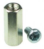
Although different sizes exist you could simply use the standard M3 chromed brass types with a length of 10 or 12 mm. I find the ones that can have screws at each side most practical. PCB mounting holes are M3 in 99% of the cases so it seems some standard exists in this world ")
With higher voltages and devices that generate heat (those often have perforated PCB's for air flow) I tend to use longer ones. I avoid the plastic types as they might be cheap but they're not sturdy.
If you build stuff more often you better keep some stock as they're cheaper too when bought in numbers. Or share with a fellow DIYer. Don't forget to buy M3 (preferably Torx as they're the standard by now) screws and M3 nuts and washers with the stand offs so you can encounter any mounting issue with ease. An investment of a few Euro and you can go on for years without any delay.
http://nl.farnell.com/ettinger/05-03-103/spacer-nickel-m3x10/dp/1466761
Last edited:
Hello,
I bought Chinese JLH kit (same as described on pages 15,16) and ordered quality capacitors and resistors.
I have TIP41c transistors in the kit. Is there are any better quality transistors for this kit (I do not want to change resistors values and so on, only replace transistors)?
Thanks in advance!
I bought Chinese JLH kit (same as described on pages 15,16) and ordered quality capacitors and resistors.
I have TIP41c transistors in the kit. Is there are any better quality transistors for this kit (I do not want to change resistors values and so on, only replace transistors)?
Thanks in advance!
Hello,
I bought Chinese JLH kit (same as described on pages 15,16) and ordered quality capacitors and resistors.
I have TIP41c transistors in the kit. Is there are any better quality transistors for this kit (I do not want to change resistors values and so on, only replace transistors)?
Thanks in advance!
Why dont you first build the kit and see how it sounds before replacing transistors ?
I'm prefer to think first and to minimise re-soldering if it's possible. Thank you!Why dont you first build the kit and see how it sounds before replacing transistors ?
Which case do you guys use for this build ? I bought a headphone case off ebay and with the standoff it looks like the board will clear the height of case.
2204E Headphone Chassis Full Aluminum Preamplifier Enclosure Amp Box PSU Case | eBay
dc
2204E Headphone Chassis Full Aluminum Preamplifier Enclosure Amp Box PSU Case | eBay
dc
Which case do you guys use for this build ? I bought a headphone case off ebay and with the standoff it looks like the board will clear the height of case.
2204E Headphone Chassis Full Aluminum Preamplifier Enclosure Amp Box PSU Case | eBay
dc
I used a Hammond 1455t2201 aluminum cabinet:
An externally hosted image should be here but it was not working when we last tested it.
For a different project I used the case that you have linked. It's a nice cabinet. However, it will be a tight fit since it is only ~4 cm in height. Although you will have little space with the heatsinks on, it is doable.
An externally hosted image should be here but it was not working when we last tested it.
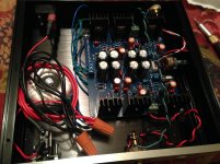
Kaplaars thanks for the info and very nice pics. As you say there is just enough space(possibly) to be able to close the lid which the case and the JLH amp. Here is a pic of my setup which unfortunately isnt as tidy as yours. Which amp did you get for your case ?
Attachments
.jpg)
.jpg)
Grounding and Connectivity check. I've been testing different points with my multimeter and hear the buzz for following
1. L/R ground
2. Secondary windings. I am guessing since there is minimal resistance in windings
3. L/R ground & transformer mount . This implies that chassis ground and L/R ground are the same ?
I have yet to hookup the power mains socket ground to chassis. What kind of wire/screw should be used for this. ? Is a 4/6 AWG solid wire sufficient ?
TIA
You're welcome . Nice work! I like the toroidal transformer, it fits very nicely. If I may give you a tip: I would try to shorten the mains / transformer leads a bit and twist all AC wires. Therewith you will minimise hum.
I really like the JHL, however I had some serious problems with fluctuating offset. To tackle this I added a DC servo circuit. It also gets quite hot. I got the advice to add some ventilation holes on top. This helped in tackle the heat quite nicely. There are quite some mods mentioned in this thread. Some are less important than others but it sure is fun to tweak the circuit a bit.
The other head amp is a clone of the Beyerdynamic A1 circuit:
. Nice work! I like the toroidal transformer, it fits very nicely. If I may give you a tip: I would try to shorten the mains / transformer leads a bit and twist all AC wires. Therewith you will minimise hum.I really like the JHL, however I had some serious problems with fluctuating offset. To tackle this I added a DC servo circuit. It also gets quite hot. I got the advice to add some ventilation holes on top. This helped in tackle the heat quite nicely. There are quite some mods mentioned in this thread. Some are less important than others but it sure is fun to tweak the circuit a bit
.The other head amp is a clone of the Beyerdynamic A1 circuit:
An externally hosted image should be here but it was not working when we last tested it.
.JPG)
An externally hosted image should be here but it was not working when we last tested it.
.JPG)
- Home
- Amplifiers
- Headphone Systems
- JLH Headphone Amp