Member
Joined 2009
Paid Member
Hi all, Bigun, where's the high value cap after the pass transistor in the John Ellis supply circuit? Just asking.
Alan
big cap? - She's not there! (que Zombies song...)
I don't think this circuit was meant to further the discussion on big caps, as far as I understand it's a regulator with loop feedback into the base of Q2 and isn't a capacitance multiplier. As I said before, I don't have any experience with regulators, whether discrete or i.c.'s which can be fussy about capacitive loads (plenty of guff to read on the Internet). The cap multiplier is what I'm looking at - I don't see a full-on voltage regulator in my current project. The disadvantage of course is that the JLH is rather sensitive to the dc supply voltage - it's idle current can move quite a bit if the supply voltage changes. That's why it needs some kind of current limiter to prevent situations where it gets too much current if a regulated supply is not being used. JLH proposed a solution or two for preventing the idle current growing too large and I plan to incorporate something.
Hi Bigun,
I was not recommending that you or anyone should build the design I posted - if anyone wanted to use that exact topology it would have to be refined, optimized etc. Rather, I was just trying to demonstrate that this topology, due to the o/p signal current flow paths, does have an simple elegance which is lost with dual rail design and I think it was a dual rail design that Andrew was referring to.
If very simple current flow paths and constant PSU current draw were considered important then I would use the design I posted and go balanced with an earth arrangement as discussed before thus keeping all of the advantages and eliminating most of the disadvantages - cap coupling etc.
I wonder how you project is progressing
cheers
mike
I also like the elegance of the Single Rail approach, but with my virtual earth I'm not adding too much complexity and the cap multiplier will be a single version placed before the virtual earth circtuit.
At the end I will have the choice which way to operate the circuit - I can operate it as a dual rail or single rail topology and listen for myself if there is enough difference for the dual rails to give up the dc speaker protect that the cap coupled output affords me.
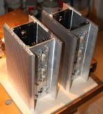
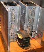
I've glued my pieces of heatsink together - added some shiny silver aluminium heatsink pieces to the black painted heatsinks that the devices are mounted on. I'm trying to use what I have to hand - it all has to come out of my junk box. I filed the edges of the black heatsinks to remove the paint from where it contacts the silver pieces to improve heat transfer. I used epoxy glue - it actually has pretty low thermal resistance and it's good for over 100 degC operating conditions.
They ain't pretty and are awkward in shape and size. I plan to have them operating with the heatsink fins vertically oriented. I will allow air to convect up the centre channel - think of them like Didcot power station cooling towers

Attachments
big cap? - She's not there! (que Zombies song...)
Exactly
Alan
Member
Joined 2009
Paid Member
Cap Multiplier
Well progress is slow due to day job but this gave me too much thinking time, now I am doubting the power supply. I thought the Cap Multiplier would be fine, but comments from others has caused some doubt.
Is the issue that there is an emitter follower in series with the amp, would a constant current supply be any better as it would present a collector to the amp instead of an emitter ?
Anybody else have some experiences to add to this topic ?
Member
Joined 2009
Paid Member
Member
Joined 2009
Paid Member
Constant current sounds inviting but wouldn't it oppose the signal in the output stage?
The signal in the output stage returns via the rail capacitors, which are placed after the cap multiplier - leaving a virtually constant current draw through the cap multiplier and allowing a CCS to be used instead. There's not much reason to use a CCS unless implementing a Shunt regulator. I have thought about this, but a Shunt regulator has it's own limitations and is another big source of heat generation. On the other hand, a CCS would help control the dc current though the output stage which tends to be unstable with respect power supply voltage fluctuations in this amplifier. Hmmm, maybe worth a thought, I think I could implement a simple shuntie here!
Last edited:
Member
Joined 2009
Paid Member
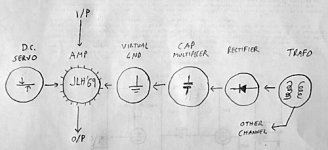
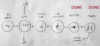
It's been slow progress but I've fixed the final design now, in my head at least. The overall architecture is shown in the attached. I'm going to start collecting all the parts together into one spot and this weekend I hope to cut up some plywood to make a kind of box for this thing.
Attachments
Member
Joined 2009
Paid Member
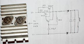
So far this project has been about following the '69 design (apart from dual rail) and using up stuff I can find in my basement. I decided to plump for a cap multiplier for the power supply. For the pass devices I had a pair of small heatsinks off another old power supply retrieved from the garbage. Each heatsink sports a pair of ancient 2N3055's which I'll use in parallel. And I also have some ancient rectifier diodes from an old power supply, 1N1200's which look pretty darn rugged - they are chasis mounting beasts.
I didn't show it in my sketched schematic, but I'll add a diode across the emitter-collector of the pass devices to prevent reverse bias of the emitter junction at turn off when the rail capacitors in the virtual earth discharge. With a bit of luck all the cap-multiplier parts will fit neatly on a small board piggy-backed to the heatsink.
Progress is still slow - it's hard to figure out how to fix all these left over parts together, it's a kind of 3-d jigsaw because there's no chasis, they all have to find a home together somehow.
Attachments
Last edited:
Member
Joined 2009
Paid Member
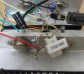
Hi AllenB - I think you have captured the problem nicely with your point-to-point wiring photo. I want something neater than that - no offense
Andrew - that's a good idea - it may be dependent on what capacitors I can find as most of my junk caps are either physically huge or have low rated voltages.
Andrew - that's a good idea - it may be dependent on what capacitors I can find as most of my junk caps are either physically huge or have low rated voltages.
- no offense
It isn't my best work
Still, just for what it's worth when it did look like that (out of a chassis) it was quiet, and my speakers are 96dB/W/m. It needed termination to eliminate some MW RF that caused some minor hum.
Member
Joined 2009
Paid Member
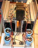
A bit more progress. I've added some angle bracket to extend the heatsinks on the outside - this will form the outsides of the chasis. The heatsink is the chasis. I'll make a front for it and a cover for the back. The back is where the power supply and amplifier will be put together. The front just has to look pretty.
I've added some angle bracket to support the trafo and installed the rectifier diodes into this bracket. This gives them somewhere to dump heat if needed (or they'll be warmed by the heatsink ) and it keeps them close to the trafo so that charging pulses are limited to short wires. The trafo is rated for 5.5 Amps; I'll only be needing 3A but I expect it will get warm.
Still gotta figure out how to mount the big caps, they've got nowhere to go to hide from the heat but I'd like to at least isolate them from direct contact with the heatsink. They'll also go close to the rectifier diodes to keep wires carrying nasty high current pulses short and sweet.
Attachments
Member
Joined 2009
Paid Member
I had time to get back to this. I've created a small wooden panel for the back to which I've mounted the big filter caps, keeping them from direct contact with the heatsink. I've mounted rail fuses for each channel, a mains switch and a fuse for it and wired them up. I've also wired up the trafo and the rectifiers. It powers up just fine, giving me two separate dc power supplies. Each channel is made up of two-phase rectifiers instead of the usual bridge/4-phase and they're wired so that each pair of rectifiers is out of phase with respect to each other so neither channel 'sees' the other channel through the power supply - giving me dual mono. It's a bit hard to see it all in the photo, the wooden panel is lying on it's back on the bench in front of the chasis but will eventually be flipped over the top of the trafo and screwed at the sides to the heatsink/chasis. It extends only part way up the chasis, leaving space for additional wooden panels as I add more functionality to complete the project. Slowly, it's coming along. The trafo does buz a little, I may try isolating it from the 'chasis' with some rubber washers.
Next step I will design a pcb that will house a cap multiplier and virtual earth along with some heatsinks for the cap multiplier power devices. These will mount on another wooden panel.
Next step I will design a pcb that will house a cap multiplier and virtual earth along with some heatsinks for the cap multiplier power devices. These will mount on another wooden panel.
Attachments
Last edited:
Hi!
Could you explain this in detail?
Maybe a drawing?
Tyimo
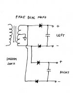
Each channel is made up of two-phase rectifiers instead of the usual bridge/4-phase and they're wired so that each pair of rectifiers is out of phase with respect to each other so neither channel 'sees' the other channel through the power supply - giving me dual mono.
Could you explain this in detail?
Maybe a drawing?
Tyimo
Member
Joined 2009
Paid Member
The way I view it, parasitic capacitances aside, the amplifier is connected to the psu transformer through the rectifier diodes only when these diodes are forward biassed and conducting. This happens at the peaks of the AC waveform. At other times the diodes are reversed biassed and the transformer is isolated from the amplifier.
In a 2-phase rectifier only two diodes are used and the transformer 'connects' to the filter caps to charge them up only once per full AC cycle. A full AC cycle (360 degrees) can be thought of as having one positive going peak and one negative going peak, alternating between them. Only one of these cycles will forward bias a 2-phase rectifier and the other cycle goes unused. So in Canada a 2-phase rectifier operates at 60Hz charging pulses instead of 120Hz for 4-phase (4 diodes or bridge) rectifier.
We can add another 2-phase rectifier connected so that it is forward biassed when the first 2-phase rectifier is reversed biassed. This means that each 2-phase rectifier takes it in turns to draw current from the transformer. Since the conduction of these rectifiers never overlaps they are fully independent of each other and behave as fully separate dual-mono supplies. In fact, they are arguably, better separated than a regular two-transformer dual mono supply. The transformer now has 4 diodes connected to it and will supply current charging pulses at 120Hz - the transformer doesn't see any difference between this dual-mono arrangement and a regular bridge rectifier.
The disadvantage is that you have a 60Hz charging cycle and so there is a longer time interval between charge pulses - larger voltage ripple on the rails requiring larger filter caps. And the ripple current rating of most caps is set at 120Hz so you need to derate it by around 85% for use at 60Hz.
Attachments
Last edited:
Member
Joined 2009
Paid Member
yes, it's a bit mad of me to do it this way but that's the joy of DIY !
One thing about independent dc rails between the channels is that I can incorporate a bit of protection - too much current flow through the virtual earth of one channel has the effect of collapsing the associated rail voltage which limits damage - this doesn't work if the other channel is not independent.
Talking of virtual earth - anybody have insight into acceptable impedance ? I plan to make a virtual earth from two bipolar complementary transistors - nothing new there. But I will use emitter resistors to control thermal runaway and I'm wondering how high I can make these resistors. For reasons I can explain later I'd like to use 10R which means my virtual earth has a 10R impedance at DC and an AC impedance equal to the reactance of the capacitors (12,200uF per rail). Thoughts ???
Last edited:
Gareth,
I use the full wave rectification for each channel, in fact two FWR for each amp module, four in all, so that no rail 'see' another. I can confirm Hotironsmoke's post that this technique offers wonderful isolation and negligible intermodulation - all from one trafo.
Nice work....
Hugh
I use the full wave rectification for each channel, in fact two FWR for each amp module, four in all, so that no rail 'see' another. I can confirm Hotironsmoke's post that this technique offers wonderful isolation and negligible intermodulation - all from one trafo.
Nice work....
Hugh
- Home
- Amplifiers
- Solid State
- JLH 10 Watt class A amplifier