Member
Joined 2009
Paid Member
I do like the dual rail rectifier design you use, it's the best approach of them all. I couldn't work out how to do it though as my Trafo has no CT and only one secondary. This project is about using up junk, my wife says I have to reduce my collection of stuff. I don't have the heart to tell her my office at work has a load of stuff waiting to come home including a 'spare' oscilloscope !
And I am also wondering if there is a connection between this hobby and cars. I remember seeing a post from you with an engine block on fire. Well I am in the process of getting a 40 year old Triumph Spitfire. Fortunately, my wife has yet to figure out that this will mean a huge pile of junk will eventually be accumulated in the garage too !
And I am also wondering if there is a connection between this hobby and cars. I remember seeing a post from you with an engine block on fire. Well I am in the process of getting a 40 year old Triumph Spitfire. Fortunately, my wife has yet to figure out that this will mean a huge pile of junk will eventually be accumulated in the garage too !
The way I view it, parasitic capacitances aside, the amplifier is connected to the psu transformer through the rectifier diodes only when these diodes are forward biassed and conducting. This happens at the peaks of the AC waveform. At other times the diodes are reversed biassed and the transformer is isolated from the amplifier.
In a 2-phase rectifier only two diodes are used and the transformer 'connects' to the filter caps to charge them up only once per full AC cycle. A full AC cycle (360 degrees) can be thought of as having one positive going peak and one negative going peak, alternating between them. Only one of these cycles will forward bias a 2-phase rectifier and the other cycle goes unused. So in Canada a 2-phase rectifier operates at 60Hz charging pulses instead of 120Hz for 4-phase (4 diodes or bridge) rectifier.
We can add another 2-phase rectifier connected so that it is forward biassed when the first 2-phase rectifier is reversed biassed. This means that each 2-phase rectifier takes it in turns to draw current from the transformer. Since the conduction of these rectifiers never overlaps they are fully independent of each other and behave as fully separate dual-mono supplies. In fact, they are arguably, better separated than a regular two-transformer dual mono supply. The transformer now has 4 diodes connected to it and will supply current charging pulses at 120Hz - the transformer doesn't see any difference between this dual-mono arrangement and a regular bridge rectifier.
The disadvantage is that you have a 60Hz charging cycle and so there is a longer time interval between charge pulses - larger voltage ripple on the rails requiring larger filter caps. And the ripple current rating of most caps is set at 120Hz so you need to derate it by around 85% for use at 60Hz.
Hi Bigun,
What you have here is actually a pair of half wave rectifiers, one each of the pair to each channel you have shown is actually redundant and can be removed.
A conventional full wave rectifier will get you both better regulation under varying load as well as approximately half the ripple amplitude at twice the frequency - which is easier to remove, easier on the cap (ripple current rating) and easier on the transformer. Half wave rectification implies the current always flows in one direction and that implies a large dc current in the secondary - carried to extremes this can even result in core saturation at relatively modest load currents particularly with toroids..
To achieve pseudo dual mono you could use a capacitive input filter with a separate choke and cap for each channel. You actually only need some mH of inductance to do this, and you get a nice quiet supply.
Ultimately outfits like Antek sell very inexpensive toroids with dual secondaries that allow you to have full isolation between the channels. If you are concerned about HF line noise getting through the transformer a combined common/diff mode choke will do the trick. (Coiltronics etc.)
Last edited:
Member
Joined 2009
Paid Member
Hi Bigun,
What you have here is actually a pair of half wave rectifiers, one each of the pair to each channel you have shown is actually redundant and can be removed.
oh yes, nice observation ! well, I'm flattered with all this advice and since I have four diodes in the box already, it seems better to 'upgrade' the wiring to a full wave rectifier.
To achieve pseudo dual mono you could use a capacitive input filter with a separate choke and cap for each channel. You actually only need some mH of inductance to do this, and you get a nice quiet supply.
I will retain the separate filter caps for each channel. As for a choke, that could be difficult. First, I don't have any of that size and this project is about using only what I have on hand and secondly, there ain't no space for adding chokes. I do have some 0.33mH chokes but I assume these are a little too small to be effective ?
The half wave rectifier just loves to have an rCRC smoothing bank after it for a quiet supply. Much more so than the full wave rectifier, but even that shows the benefit of the extra stage of filtering.
Have a look at the multistage filtering used by the Tube/Valve guys where capacitance becomes very expensive.
Have a look at the multistage filtering used by the Tube/Valve guys where capacitance becomes very expensive.
Member
Joined 2009
Paid Member
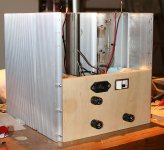
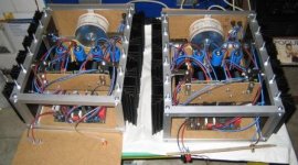
Well, a couple of short wires added and it's all happy as a full-wave rectifier. I've added an 0R51 into the positive rail between the two big blue filter caps of each channel. The rectifier still 'sees' two big blue caps in parallel, being the first big blue cap on each channel. Yeah, I wimped out on the half-wave rectifier, maybe another time. And yes, power switch is on the back panel. This is a Class A amp, it won't be constantly switched on and off so I'd rather hide the switch at the back and keep mains AC wiring in a small space. I've got earth wires screwed to 4 separate spots on the chasis for safety.
Photo shows the wooden panel flipped up and screwed in place. This is the back of the amp starting to take shape. The next strip of wood to be mounted on the back will be the cap multipliers, plenty of work still to sort them out. I figure that those big blue caps at only 11,000uF each aren't going to be enough for a quiet supply on their own. On the same board I'll include the virtual earth which will have rail to ground bypass caps of 10,000uF per rail per channel, each bypassed by a 2,200uF Nichicon MUSE gold cap.
Above the cap multiplier module there'll be a gap at the top for another wooden strip which will hold the front end of the amp.
It's pretty crowded in amongst the trafo and those big filter caps and I'd like to run a check on how warm it gets when loaded. Before I can connect a dummy load to the power rails to do that, I need to install suitable fuses. The rail fuses in there right now are 250mA as that's what was in the holders when I pulled them off a scrap item. Once I've found a pair of 2A or 3A fuses I'll be able to run some serious juice and see more clearly how ugly this thing is.
Attachments
Last edited:
Member
Joined 2009
Paid Member
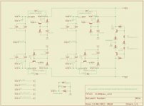
I decided this project is an opportunity to learn and do something new - namely use a proper pcb layout software. I picked Eagle because I have a Mac and it works on a Mac, it's a very usable tool and did I mention it's free within certain limits 
First off is to set up a schematic of the power supply - namely the virtual earth, the protective earth (which keeps the signal ground isolated from safety earth in a safe fashion) and the emitter follower regulators (cap multipliers to you). There's an emitter follower per rail per channel, so four in total. And I happen to have two small heatsinks from an old bench supply with a pair of 2N3055s on each one - perfect for the job of using up my junk - which means the pass devices are off-board.
The rectified and filtered dc power enters from stage right on this schematic.
I've attached an image of the schematic, comments welcome.
Attachments
I decided this project is an opportunity to learn and do something new - namely use a proper pcb layout software. I picked Eagle because I have a Mac and it works on a Mac, it's a very usable tool and did I mention it's free within certain limits
First off is to set up a schematic of the power supply - namely the virtual earth, the protective earth (which keeps the signal ground isolated from safety earth in a safe fashion) and the emitter follower regulators (cap multipliers to you). There's an emitter follower per rail per channel, so four in total. And I happen to have two small heatsinks from an old bench supply with a pair of 2N3055s on each one - perfect for the job of using up my junk - which means the pass devices are off-board.
The rectified and filtered dc power enters from stage right on this schematic.
I've attached an image of the schematic, comments welcome.
The first thought that comes to mind is your capacitance multipliers are throwing away roughly half your supply voltage by virtue of the 24K resistors configured as a voltage divider - did you really mean to drop the voltage by half..
The active supply splitter seems to argue for a full wave rectified supply with center tap, simpler and more reliable in the long run.
The addition of a single additional transistor, a zener, a small cap for miller compensation and a couple of resistors to each of your capacitance multipliers would give you an actual discrete voltage regulator if you wanted a really low source impedance, a well defined supply voltage and less noise.. (Put a reverse biased clamp diode across each output to make sure they start if you do this..) I did something similar with a darlington and a somewhat more sophisticated VAS, it worked well.
Member
Joined 2009
Paid Member
Lose half the supply voltage ! well, then we don't want 24k resistors in the cap multipliers. I want to limit the drop to around 2V to 4V at most, so I'll have to recalculate.
However, I have already converted over to full phase recitification so we're ok on that score.
In terms of upgrading to voltage regs. It's an interesting question. The downside is more power dissipation into the smallish heatsinks the pass devices are sitting on and I only have 4V at most to play with that can be dropped across the regulators before I start running out of steam. In my junk box I have a good supply of LM317 regulators that could be pressed into use here but I detect a disdain for gnf based regulators in power supplies for power amps around this Forum ???
Last edited:
Lose half the supply voltage ! well, then we don't want 24k resistors in the cap multipliers. I want to limit the drop to around 2V to 4V at most, so I'll have to recalculate.
However, I have already converted over to full phase recitification so we're ok on that score.
In terms of upgrading to voltage regs. It's an interesting question. The downside is more power dissipation into the smallish heatsinks the pass devices are sitting on and I only have 4V at most to play with that can be dropped across the regulators before I start running out of steam. In my junk box I have a good supply of LM317 regulators that could be pressed into use here but I detect a disdain for gnf based regulators in power supplies for power amps around this Forum ???
Provided that the input power is pretty stiff you might get away with relatively little drop. I was suggesting a discrete design - not a monolithic, note that you can also bypass some percentage of power around the regulator with a power resistor in order to keep dissipation reasonable, the low source impedance at the emitter of the pass transistor and the closed loop performance of the regulator should dominate even with a resistor between collector and emitter.. (And it assures the regulators start up properly) I usually bypass about 1/3 of the load current around the regulator - note that this only works with class A amps and filament loads..
In this case it would allow you a little more headroom for high and low line conditions..Member
Joined 2009
Paid Member
Looking at the 'numbers' I can't afford any voltage drop associated with the use of voltage regulators for the power rails. Saves me from wondering if I want a voltage regulator - I suspect it has it's share of problems.
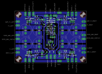
My first time using Eagle, single sided layout of the psu board with cap multipliers, virtual earth and protective earth. First draft attached... remember that the pass devices are off-board.
My first time using Eagle, single sided layout of the psu board with cap multipliers, virtual earth and protective earth. First draft attached... remember that the pass devices are off-board.
Attachments
New to the JLH world
Hi all,
A few words to introduce myself as a new member of the JLH owner's group.
I finished a coupled of days ago the building of the first mono-bloc of a JLH 1996 updated version based on ON MJ15003 dual matched pairs for Q1 (a,b) and Q2 (a,b) and Toshiba 2SC2911 for Q3 as suggested earlier in a post this year.
It is currently set-up at 19V and 2,8A as a quiescent current (1,4A through each of the OR1 at the emitter of the 4 MJ15003). I did initial listening with some old self-made speakers to verify the potential hum. So far, so good.
On top of this thread and Geoff's site, usefull information came from JLH-2005 – NOTES
I'm happy to share, would anyone be interessted, the PCB(s) layout for the PSU - I modified slightly the negative rail's circuit to use BD140 / MJ15004 transistors - and the part list I put together.
I will certainly raise a few questions over the coming weeks while I test and try to figure out more and more the bits and tricks...
Cheers,
Jean-François.
Hi all & Alan,
This forum is a real great source of information which I enjoy since I started thinking about building a multi-channel's sound system.
The JLH is my first DIY amp - not far from being the first DIY electronic gear - so lot of things to learn every day
Each channel is built with a symetrical regulated power supply from a 2x18V - 230VA toroid and 4 MJ15003. Each of the MJ15003 runs 1,4A based on the voltage on the 0R1. Is my understand correct that this makes a quiescent of 2x1,4 = 2,8A?
So far, I tried to run it up to 20V and 1,8A per MJ15003 and thermal stability looked to be OK.
It is not yet connected to the main hi-fi system but to low bandwidth speakers so it is really difficult to judge at this stage the sound in a perfect way. What I can say is that the sound is very transparent and detailled compared to the keenwood amp seating on the test system as an A-B comparison point.
Cabling is still in progress - not organized / twisted by transistor or optimized in lenght, shielded cable still needed for audio signal input and the Vellman kit for speaker protection is waiting to be connected. Pannels are all in MDF wood pending final decision on how it will look like.
Below a few pictures:
- PCB(s) for the power supply of the second mono-bloc : bridge rectifier is based on MBR20100CT schottky diodes and regulators are using TL431 CLP.

- Heatsinks cut from a 1 meter block into 16 cm pieces (an aluminium windows manufacturer / installer agreed to cut it for me with a profesionnal saw). They are supposed to be 0,6°C/W from the manufacturer's specifications.

- Side views, front views, pannel view of the existing mono-bloc (in its present state)...


I've not used copper plates to connect the power supply main capacitors as seen in many implementations. Is it needed ? Would it bring any benefit?
Both positive and negative parts of the power supply are completely independant in term of zero volt reference point until they connect to the amplifier board and the ground star point is at the audio signal entry point linked with the main's earth point.
Cheers,
Jean-Francois.
This forum is a real great source of information which I enjoy since I started thinking about building a multi-channel's sound system.
The JLH is my first DIY amp - not far from being the first DIY electronic gear - so lot of things to learn every day
Each channel is built with a symetrical regulated power supply from a 2x18V - 230VA toroid and 4 MJ15003. Each of the MJ15003 runs 1,4A based on the voltage on the 0R1. Is my understand correct that this makes a quiescent of 2x1,4 = 2,8A?
So far, I tried to run it up to 20V and 1,8A per MJ15003 and thermal stability looked to be OK.
It is not yet connected to the main hi-fi system but to low bandwidth speakers so it is really difficult to judge at this stage the sound in a perfect way. What I can say is that the sound is very transparent and detailled compared to the keenwood amp seating on the test system as an A-B comparison point.
Cabling is still in progress - not organized / twisted by transistor or optimized in lenght, shielded cable still needed for audio signal input and the Vellman kit for speaker protection is waiting to be connected. Pannels are all in MDF wood pending final decision on how it will look like.
Below a few pictures:
- PCB(s) for the power supply of the second mono-bloc : bridge rectifier is based on MBR20100CT schottky diodes and regulators are using TL431 CLP.
- Heatsinks cut from a 1 meter block into 16 cm pieces (an aluminium windows manufacturer / installer agreed to cut it for me with a profesionnal saw). They are supposed to be 0,6°C/W from the manufacturer's specifications.
- Side views, front views, pannel view of the existing mono-bloc (in its present state)...
I've not used copper plates to connect the power supply main capacitors as seen in many implementations. Is it needed ? Would it bring any benefit?
Both positive and negative parts of the power supply are completely independant in term of zero volt reference point until they connect to the amplifier board and the ground star point is at the audio signal entry point linked with the main's earth point.
Cheers,
Jean-Francois.
Member
Joined 2009
Paid Member
Jean, that's looking great ! - I'm most jealous as my own is making very slow progress due to family, day job and my ineptitude
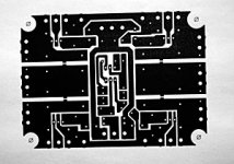
I've had a devil of a time getting the laser printer I have access to at work to print out the toner image of the pcb. It's a new printer. I'm using glossy paper, torn out of a US Electronis hobbyist magazine. This approach was successful in the past on my TGM project. I spent 3 hours to no avail. All I could get was an image on regular paper (see attached).
Then I realized, this is a JLH design, it's British. So the next day I took in an English Hi-Fi magazine and used a page from that. Worked like magic
Next issue was that I've tidied up the wiring around the psu trafo, rectifiers and cap quite significantly. But the darn thing buzzes loudly when powered up. It's unbearable from the other side of the room. I pulled out the screws that were firmly holding the trafo via 4 brackets to the chasis and then put a rubber grommet under each corner with no screws. It was silent. So there's a way forward, I just have to find some longer bolts to hold it together.
Attachments
Buzz...Buzz...Buzz...
Bigun, all
I used myself an inkjet printer and slideshow paper to print the pcb layout... the inkjet printer has been purchased in Singapore, is using ink cartridges imported from Taiwan and printing a British layout on French paper...
This could be the reason I have some hum and buzz now....
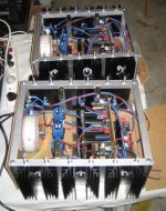
More seriously, I finished mounting / wiring the second mono-bloc (pictures attached) and I'm facing a situation now where:
1) Each mono-blocs is dead silent when connected alone to the pre-amplifier. No hum or buzz in the speaker when not playing music and sound is fine.
2) As soon as I connect both mono-blocs to the pre-amplifier, a buzz is heard in both channels.
3) If I switch off one mono-bloc leaving it connected to the pre-amplifier, the buzz remains in the speaker of the second mono-bloc
4) I tried by-passing the pre-amplifier by connecting to the CD player directly, and the same buzz can be heard.
I'm quite sure that this is an earthing issue but don't know really at this point where to start from. I'm going through the forums to find out if any-one had an equivalent issue before.
Advices are welcome to help !
Thanks,
Jean-François.
Bigun, all
I used myself an inkjet printer and slideshow paper to print the pcb layout... the inkjet printer has been purchased in Singapore, is using ink cartridges imported from Taiwan and printing a British layout on French paper...
This could be the reason I have some hum and buzz now....
More seriously, I finished mounting / wiring the second mono-bloc (pictures attached) and I'm facing a situation now where:
1) Each mono-blocs is dead silent when connected alone to the pre-amplifier. No hum or buzz in the speaker when not playing music and sound is fine.
2) As soon as I connect both mono-blocs to the pre-amplifier, a buzz is heard in both channels.
3) If I switch off one mono-bloc leaving it connected to the pre-amplifier, the buzz remains in the speaker of the second mono-bloc
4) I tried by-passing the pre-amplifier by connecting to the CD player directly, and the same buzz can be heard.
I'm quite sure that this is an earthing issue but don't know really at this point where to start from. I'm going through the forums to find out if any-one had an equivalent issue before.
Advices are welcome to help !
Thanks,
Jean-François.
Attachments
How many times do we need to remind Members to read what is on the Forum?
Audio Component Grounding and Interconnection - diyAudio
Audio Component Grounding and Interconnection - diyAudio
Member
Joined 2009
Paid Member
progress or no progress ? - well I didn't make the pcb for the cap multipliers. Something just wasn't right, nagging at me. I'm ditching the cap multipliers. I now think they are the wrong approach because they put a non-linear element into the current. I thought it would be enough to add lots of capacitors afterwards but it requires a lot of high quality capacitors in my view to avoid the impact of the cap multiplier and the capacitors on the sound.
I'm going to build without the multipliers and see how much hum I get. In the meantime, I will consider the idea of using a JLH Ripple Eater.
I'm going to build without the multipliers and see how much hum I get. In the meantime, I will consider the idea of using a JLH Ripple Eater.
Hi Bigun,
On my side, I fixed the PIN-1 issues on both monoblocks that was participating to the buzz of the setup. The buzz has reduced a lot but not fully disapeared. I'm doing measurements between chassis, power ground, earth safety ground, signal ground to see how the whole thing behaves. I started rewiring the grounding completely on one mono-block to have an A-B comparison point. The next steps will be to implement some shielding, doing physical layout changes, implementing a ground loop breaker.
Regarding the PSU, I'm contemplating the idea to implement two PSU, one with voltage regulation for the first two stages and one with C-R-C or C-L-C style filtering for the last stage. I've seen this in a class A amp as the needs are quite different between these two parts of the amplifier but don't know yet how this would work here.
The first step will be to do some simulation using SPICE - good activity for summer break rainy days to learn new things
Cheers,
Jean-François.
- Home
- Amplifiers
- Solid State
- JLH 10 Watt class A amplifier