 OOOOOOOOOOOOOOOps! jonathan is right, seems l got a bit beffudled with all the different device numbers and in my slightly delicate condition is it any wonder?, yes l did mean 3055's,
 sorry for the confusion this may have caused
 and nordic congrats in getting the toshiba devices to work so well as it was documented by geoff that others who tried to use them had oscillation problems with them though they are a great device, the secret must be in your layout l think, cheers, TC
Sadly I do not have a scope, so I can not guarntee it does not ring a little...
However there is no AC (that I can measure on my multi meter), nor do I hear any muffling or overbrightness. And the Transistors gets warm nice and gradualy, but obviously due to my too small sinks are unlikely to hit a thermaly safe operational point yet. also no hum, it will even reproduce the ground noise his in music, but goes dead quiet in between tracks...on a pretty efficient 8ohm driver.
Not to be held back I am allready modifying the board to add better regulation for the two front taps to the V+ rail. I want to hear the change in sound for myself.
I expect it to be a change for the better as I do not like traces drawing uA, mA and 2A connected together.
And I guess it will be totaly unsuitable for MP3's afterwards, as it is allready painfull listening to the artifacts in some badly compressed stuff.... (I have showed my wife 100 times, and she still messes it up). Luckily I only use MP3 sources for innitial testing... (one less ground loop to worry about)
No ringing on any square wave with my version I cobbled together a few years ago. Not done much with it, though - a kind of exercise to use up some old BDY 56's I've got (or a shed load of 3055's). So I thought I'd take some measurements last night. THD fine, but it doesn't seem to like 8R//2u2 yet.
Brian.
Brian.
Attachments
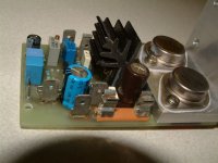
Wow, thats what I call a thermal interface...
I have to say, I am getting obsessed with this sound....
I sneak in as much time as the heatsink can handle, whenever I get a chance...
Its been a while since I fell head over heals in love with an amp.
My eye caught a class AB JLH claiming to sound as good /indistinguishable from the class A. A claim I find hard to swallow. Guess I'll try it in the long run ,but the 69 JLH suits my transformers, and that of most old gainclones... I wish DIY designers would start their designs first looking at which transformer voltages are the most common.
This is the ugliest (yes, even my first dead bug GC looked more elegant), yet best sounding prototype I have ever built. Lots of people claim their amps have a valve like sound... this is as close to it as I think one can come.
Nordic said:Sadly I do not have a scope, so I can not guarntee it does not ring a little...
Nordic
To set your mind at rest a little, I have heard from a couple of people who have used 2SC5200 output transistors in the 1969 version (without additional compensation) and they have not been able to detect or measure any instability. Others have been less fortunate, probably due to layout.
Later versions seem to always oscillate when faster output transistors are used. I put the more benign nature of the 1969 version down to the fact that the bootstrap capacitor loses its effectiveness at high frequencies thus changing the load on Q3.
I am pleased that you have joined the many hundreds, or rather thousands, of constructors who have found the JLH to be rather pleasant sounding (deliberate understatement!).
Geoff
What does C5 DO?
I tested with and without... I got 100u in there now...
Better attack with it, but I need to compare with takeing it out again, unless it has some important function. Hard to compare, because in between installing it, the PSU ate some caps... swapped the 10000ufs for 2x 4700uf now, still no hum...
Guess I need to do a soft start, and here I was thinking you only need those with toroidals...
Would it be enough to just delay the speaker connection with one of my speaker protection modules to reduce the power on spike?
I noticed I am no longer hearing what I believed to be background noisefloor with music playing, so that may be an artifact of this cap... looks like a bootstrap.
Nordic said:What does C5 DO?
There isn't a capacitor labeled C5 on the original 1969 schematic.
If you are referring to the 100uF electrolytic adjacent to R5 then this forms a low-pass filter in conjunction with the 39k resistor connected to +V in order to reduce the amount of supply rail noise that is fed into the input of Q4.
A better input biasing arrangement is that shown in:
http://www.tcaas.btinternet.co.uk/jlh2000.pdf
Rather pleasant sounding indeed. Even very old recordings seem to sound better. Mine hasn't made it out of the basement.Geoff said:
I am pleased that you have joined the many hundreds, or rather thousands, of constructors who have found the JLH to be rather pleasant sounding (deliberate understatement!).
Good to see your name here again, Geoff.
Paul
http://www.tcaas.btinternet.co.uk/jlh2000.pdf
The one connected close to the bias pot going to the output.
I understood this to be a copy of the original concept... I looked at the actual 1969 document now, which calls it C1 and offers some description of it influenceing LF response.
The one connected close to the bias pot going to the output.
I understood this to be a copy of the original concept... I looked at the actual 1969 document now, which calls it C1 and offers some description of it influenceing LF response.
Nordic
OK, we'll use the schematic in the jlh2000.pdf.
You cannot omit C5. It is essential for correct circuit operation. C5 is the bootstrap capacitor and it ensures that the dc bias current for the output stage remains relatively constant.
C5 ensures that, in the presence of a signal, the ac voltage on each side of RV1 is the same. This means that the voltage across RV1 is constant resulting in a constant current being fed to the Q2b/Q3c junction.
Use a minimum of 220uF for C5. 470uF brings a sonic improvement. There is no benefit in going higher than this.
Geoff
paulb said:Good to see your name here again, Geoff.
Thanks, Paul.
I've been around most of the time, just not been posting very much.
Geoff
Indeed good to hear from you Geoff....
btw... off topic..
Just recently I downloaded a PDF of a very interseting JLH article.. .. called something like "Refernece RIAA headphone amplfier". It contained a "super linear gain block" description .. consisting of a single-gain-stage , cascoded and CSS JFET.. very interesting!
If I can find it, I'll send it to you so you can put it on you website.
cheers,
Thijs
tschrama said:Indeed good to hear from you Geoff....
btw... off topic..
Just recently I downloaded a PDF of a very interseting JLH article.. .. called something like "Refernece RIAA headphone amplfier". It contained a "super linear gain block" description .. consisting of a single-gain-stage , cascoded and CSS JFET.. very interesting!
If I can find it, I'll send it to you so you can put it on you website.
cheers,
Thijs
Hi Thijs
Thanks for the offer but I think I have a copy of that article. If it is available elsewhere on the web then I won't duplicate it on my website.
Geoff
Hi tschrama
I would be very interested if you could send me a copy of that pdf.
When i was 18 i built a preamp that was sold as kit called the jlh preamp. In the confusion of emigrating to europe very very sadly this preamp got lost and i would like to get as much info on it as i can. I believe the phono section on the pdf might be the one used in this preamp. At that time i made various comparisons with other preamps and my its a beauty. My brother in law which is a sound engineer couldnt believe that a preamp i paid around 15 euros at that time could outperform his i think it was a JC1 or JC2 preamp he had. He did and still has very expensive equipment including linn sondek turntables. That preamp is brilliant but i havent been able to find any schematics on it yet.
Could anyone else here help?? This preamp is from around 1988 1990 thereabouts.
homemodder said:Could anyone else here help?? This preamp is from around 1988 1990 thereabouts.
JLH published two pre-amp designs around that time, in Wireless World 1982/3 and in ETI 1992 (April/May).
The 1992 ETI design was sold as a kit by Hart Electronics but the earlier WW one was not (so far as I am aware).
Hi all
the faster ouput transistors give a much better slew rate, and lower distortion (more linear gain).
I mentioned somewhere earlier in this thread (I think it was here) that I used a small compensation capacitor around the feedback resistor to stabilise the design (and yes, this simulates the same result too: its not just layout) when using faster Tr's.
cheers
John
I mentioned somewhere earlier in this thread (I think it was here) that I used a small compensation capacitor around the feedback resistor to stabilise the design
Indeed you did. As a result I've applied 47 pF around the feedback transistor when I started using fast output transistors (2sc3281).
Never used a scope to verify things, but I've found no behaviour which indicates the amp being unstable or oscillating.
MArco
tschrama said:I am going to look for it tomorrow.
It is a fascinating article, single gain stage, very ZEN-like.. and in light of the JFET BOZ, make excelent reading...
cann't find the website anymore, but I must have the PDF here somewhere.. check back tomorrow..
chrzz, Thijs
File is 1.5MB.. it's too big to post here..
- Home
- Amplifiers
- Solid State
- JLH 10 Watt class A amplifier