bi-amping
Chris,
My current system:
Pre-amp => high crossover => cable => tweeter
=> low crossover => cable => woofer
Is going active worth it?
I believe so. Reading all kinds of literature it has real advantages.
- less, smaller components => same money better components
- every amp has to work less
- and so on.
Recommended reading:
Nelson Pass: http://www.passlabs.com/pdf/spkrcabl.pdf
http://www.passlabs.com/pdf/XVR1MAN1.PDF
John Broskie (two articles) http://www.tubecad.com/page4.html
And of course this forum.
Luuk
Active crossover
Hi,
what crossover do yo plan use ?
a diy or a finished one.
Which psu did you use?
Regards,
Ralf
chris ma said:NickC,
Sorry I lied, the transformer I am using is 300VA 22-0-22 not 18-0-18 as stated previously.
I used the variac to bring the amp up slowly and monitor the components and the heat along the way, so I get a rough idea what gets hot and what not in the first place. Most of the time people get burn is the unexpected contact, like I tend to burn myself when I change hands with the soldering iron, just grab the metal part of the iron instead by mistake.
How is your project coming?
Bosssenkool,
When you bi-amp without a cross-over (on the way I know) for now, don'you get overlap of certain frequency range between the Hi and Low, assuming you have not remove the passive crossover network in your speakers, so you are really bi-wire with two amps? If it has no problem then why one need to go the extra step to go active crossover?
Regards,
Chris
Hi,
what crossover do yo plan use ?
a diy or a finished one.
Which psu did you use?
Regards,
Ralf
Hi Willy,
I can recommend these pages:
http://www.gmweb.btinternet.co.uk/
http://sound.westhost.com/jll_hood.htm
They should give you all the information you need.
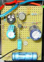
The JLH 10 Watt Class A amplifier is a nice simple project. Once I finished mine, I haven't used my sony or technics amp since. Goodluck with your project.
Greetings,
Thijs
Hi Ralf,
The idea that I have is mind, is to follow the simple route (taken by others, including Nelson Pass).
Simple diy 1st order filter:
Diagram High:
pre-amp -> C -> | -> Amp -> Tweeter
R
|
earth
Diagram Low
pre-amp -> R -> Amp -> Woofer
|
C
|
earth
At first no opamps etc, see how it works,
I don't know what you mean with the psu question.
Greetings,
Luuk
Re: JLH
If you're reading this, thank you again, Geoff!
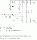
I have a single-supply version of this circuit that Geoff provided for me. I'm in the middle of building a version now.Les said:Hi All here is a circuit that was e-mailed to me by Geoff Moss
If you're reading this, thank you again, Geoff!
JLH, modified 1996 version.
I wish to point out an error in the JLH amplifier circuit that Les has posted on this thread. The value of VR1 in the offset ccs control should read 2K, not 200 ohms.
I have been using this circuit (apart from the value of VR1) for some time now. In my opinion it improves considerably on the standard 1996 version in many areas. Recently, the feedback capacitor has been replaced with a wire link, with VR1 reduced in value for ease of adjustment, to good effect. The DC offset is now more difficult to adjust, but the hot/cold offset variation is not significantly worse than it was in the standard 1996 version. Components used include Elna silmic electrolytics, Audio Note paper in oil capacitors and A.N. tantalum film resistors. I prefer the A.N. resistors/capacitors to other types due to their clarity and lack of hardness. The power supply is a capacitance multiplier with separate regulators for each channel, quite an improvement on the single version but with some adaptation needed to enable the voltage on each channel to be adjusted independently.
Considerable credit must go to Geoff Moss, who helped with the circuit modifications.
Tim.
JLH 1996 version modification results.
I think I will elaborate a little on my previous post in this thread.
The following is a list of the modifications that, with considerable help from Geoff Moss, I have carried out over the past year on the 1996 standard version of the JLH, and my opinion of the results of those modifications. Each substitution has been carried out individually to enable subsequent and hopefully accurate (but not always positive!) evaluation.
Professionally, I have a very close affinity with the piano, a difficult instrument to record, as well as reproduce. It is my view that any modification that produces a more realistic rendition of the complex and sometimes very subtle structure of the sound of this instrument, will also represent an improvement in the accuracy of the amplifier in general, as has been the case during all my listening trials.
Amplifier.
1. Replace 2N3055 with MJ15003.
2. Replace 2N1711 with 2SC3421.
3. Replace BC212 with 2SA970.
4. Replace 7815 with constant current source.
5. Replace Iq control circuit with bootstrap (Elna Silmic) circuit.
6. Replace Iq control circuit with c.c.s.
7. Remove 470uF Oscon (previously 220uF Silmic) feedback capacitor, replace with link and change VR1 to 200 ohm.
Results.
1. Comprehensive and very substantial improvement.
2. Improved detail and smoothness with better defined tonal colour.
3. Similar to above.
4. Substantial improvement in both smoothness and detail. Improved low level ambience.
5. Less clarity with less tonal variety and focus, sounding more shut-in. This one was quickly removed.
6. Less 'lively', more natural treble with greater 'hear-through' quality to harmonics. Less 'impressive' but considerably more musically rewarding.
7. Greater detail and smoothness, better space and ambience.
Power supply.
1. Bypass reservoir caps with 100uF Silmic.
2. Install snubbers across rectifier diodes.
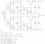
3. Replace LM338K regulator circuit with capacitance multiplier.
4. Replace single capacitance multiplier with new (adapted) dual version allowing separate c.c.s. regulation for each channel.
Results.
1. Slight improvement in clarity, possibly.
2. No improvement was noticed.
3. Subtle improvement in smoothness.
4. Substantial improvements across the board, well worth it.
Tim.
Re: JLH, modified 1996 version.
I can concur with the results after removing the feedback capacitor. Sound becomes more vivid and real without that cap. DC offset is harder to trim but it’s possible.
Concerning the rest of the circuit I still prefer the original bootstrap arrangement over Iq ccs for some reasons. With the rest off the components in my system treble became little too over pronounced with Iq control circuit with ccs. But I would imagine that with non-os dac where you need to compensate for a slight treble loss, Iq ccs could be a preferred solution.
Argo
Re: JLH 1996 version modification results.
Hi, Tim,
Do you have details on 4? Is it simply a constant current source
from the positive voltage rail to the emitter of Tr4 (which you
replaced with 2SA970)? If it is that, what did you do for the
collector of Tr4?
Finally, what is the Iq control circuit of 5 and 6? I've been
referring to Fig. 3 at http://www.gmweb.btinternet.co.uk/jlh1996.htm .
Am I even looking at the right circuit?
Thanks for posting your results. They are very interesting, and I
may well try building one of these amps before the year is out
using most of your improvements.
Thanks,
Erik
TimA said:
Amplifier.
1. Replace 2N3055 with MJ15003.
2. Replace 2N1711 with 2SC3421.
3. Replace BC212 with 2SA970.
4. Replace 7815 with constant current source.
5. Replace Iq control circuit with bootstrap (Elna Silmic) circuit.
6. Replace Iq control circuit with c.c.s.
7. Remove 470uF Oscon (previously 220uF Silmic) feedback capacitor, replace with link and change VR1 to 200 ohm.
Hi, Tim,
Do you have details on 4? Is it simply a constant current source
from the positive voltage rail to the emitter of Tr4 (which you
replaced with 2SA970)? If it is that, what did you do for the
collector of Tr4?
Finally, what is the Iq control circuit of 5 and 6? I've been
referring to Fig. 3 at http://www.gmweb.btinternet.co.uk/jlh1996.htm .
Am I even looking at the right circuit?
Thanks for posting your results. They are very interesting, and I
may well try building one of these amps before the year is out
using most of your improvements.
Thanks,
Erik
You should look at the history of the amp design for context.
The original JLH:
http://www.gmweb.btinternet.co.uk/jlh1969.htm
The 1996 revision:
http://www.gmweb.btinternet.co.uk/jlh1996.htm
A high current version done by Geoff and Nick Gibbs: (Feb 2002)
http://www.gmweb.btinternet.co.uk/jlhesl.htm
An updated version of this last appears earlier in this thread (page 10). I also have a single supply version of this circuit kindly provided by Geoff.
Plus the mods noted just a few posts earlier.
Erik,
The answer to your first question was posted recently by Les. My circuit is the same in most respects.
You are correct in your assumption that the Iq control circuit that was replaced in 5 and 6 is that of figure 3, http://www.gmweb.btinternet.co.uk/jlh1996.htm.
Incidentally, with the (standard 1996) circuit I noticed the most pronounced treble. With the bootstrap arrangement, the treble became considerably less pronounced, but slightly coloured, with a less subjectively extended bass and a homogeneous quality overall. The Iq ccs retained the clarity and open sound of the standard version but with a more organic quality in the treble, and without the detrimental effects of the bootstrap. However, I would imagine much would depend on the choice of bootstrap capacitor.
Tim.
- Home
- Amplifiers
- Solid State
- JLH 10 Watt class A amplifier


