MJ15003 I think is identical to 3055A except power dissipation. The model I took from ON semi.
Lately, I simed the Dual cv30 and I was surprised to find exactly the same distortion curves both 1khz and 10khz given in the manual.
Here is Tina file.
Lately, I simed the Dual cv30 and I was surprised to find exactly the same distortion curves both 1khz and 10khz given in the manual.
Here is Tina file.
Attachments
Last edited:
Well, I've developed SPICE models. It takes some time when you don't have ideal kit. I'm working through the list of devices. Which is why I had a more representative 2N3055H model than the available one. And models for various devices which are otherwise not so good. And I have also contacted a well known manufacturer who only sent a "yes but" response.
I would not generally make these available for others to use as they are not exhaustively tested - such as fT with temperature. And the main problem is knowing if you have a really typical device.
The reason manufacturers are best placed is that they have the statistical data (or should have) and therefore be able to select a really typical device for SPICE model development.
Individual transistor data does not guarantee that. Datasheet data does not contain all the results needed.
Furthermore, manufacturing targets may change with time. Datasheet specs ought to be updated along with models if such changes occur. The "hard" data of course still stands, but typical might change with time.
I'm sure you know that, really.
Last edited:
I have not sat and waited, though, have I!
It does not change my view that manufacturers are in the best position to provide accurate data reflecting typical (and best/worst) case models.
But I do have several SPICE models representing individual devices I have measured. It is whether that is typical or not is my point.
It does not change my view that manufacturers are in the best position to provide accurate data reflecting typical (and best/worst) case models.
But I do have several SPICE models representing individual devices I have measured. It is whether that is typical or not is my point.
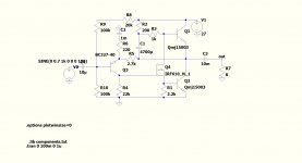
@kokoriantz - I don't get your low distortion figures with IRF610 driver. To get anywhere near close I used a 2N7000. Smaller device, less gate current needed (almost 1/10) and then only with a compensation cap of 10pF to stop a little oscillation. That used the On Semi /MODPEX model MJ15003.
0.09% at 9.5W/10kHz but also 30V rail. Think that the dissipation with reasonable gain transistors is within the power limit of the 7000 (400mW -maybe add a heat clip to it). 15003's in my sim only needed ~8mA in the 7000 = 120mW.
0.09% at 9.5W/10kHz but also 30V rail. Think that the dissipation with reasonable gain transistors is within the power limit of the 7000 (400mW -maybe add a heat clip to it). 15003's in my sim only needed ~8mA in the 7000 = 120mW.

What makes the IRF610 lower distortion is the possibility of higher input resistance 22k instead of 8.2k. Higher open loop gain hence lower distortion.
I tried with C5200 transistors, the distortion is still lower to 0.012%.
I tried with C5200 transistors, the distortion is still lower to 0.012%.
Attachments
Last edited:
I tried to sim with LTspice, I downloaded the most recent models. The mj15003 has too high Hfe, but on Tina it gives 0.015% for 5.5W. The model of IRF610, the LT doesn't read. I am a novice with this simulator, if someone can make it work. A similar but older model was used here IRF610 Class A Headphone Amp.
Attachments
Higher open loop gain hence lower distortion.
Higher open loop gain hence higher distortion.
The mj15003 has too high Hfe
Hence too high distortion.
The model of IRF610, the LT doesn't read. I am a novice with this simulator, if someone can make it work.
You have to enter the complete name of the component, as written in the .model = IRF610_N_1
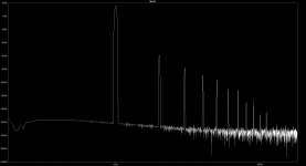
I did a quick test, and get 2nd harmonic @ -76dB like this (falling higher harmonics).
Remember to disable compression in the control panel.
EDIT: calculated wrong, I wrote -86 first. Can probably be tuned to better performance, this was a quick test.
Remember to disable compression in the control panel.
EDIT: calculated wrong, I wrote -86 first. Can probably be tuned to better performance, this was a quick test.
Attachments
Last edited:
Higher open loop gain hence higher distortion.
Hence too high distortion.
Sorry for my error. Of course lower distortion.
This model is what I got from Tina netlist. Why the long one is not recognized, it saysYou have to enter the complete name of the component, as written in the .model = IRF610_N_1
*appropriate data sheet of the same number for guaranteed specification
*limits.
.SUBCKT IRF610 1 2 3
**************************************
* Model Generated by MODPEX *
*Copyright(c) Symmetry Design Systems*
Here is what I got with your standard circuit. Same distortion performance. I only improved the current sharing between the outputs (and better LF performance) with my tweak, so it should give more output current compared to Iq.
I'm not sure what you mean in reference to Tina? I'm no expert in the details of the models..
I'm not sure what you mean in reference to Tina? I'm no expert in the details of the models..
Attachments
Well, sorry if there was some misunderstanding - seems we were not comparing like for like.
I ran my earlier FET sim at 20kHz and near peak output. I do that almost automatically as that needs to be good for audio. In my book.
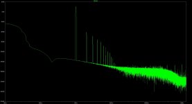
I reran my simulation with an IRF610 at 1kHz and 700mV input, and get -70 something dB second harmonic, and .055% THD. (Default plot is in volts in SIMetrix).
My earlier comments referred to 20kHz and near clipping output (9.5W) with 935mV input.
Yes, I noted the change to 22k and included that in my original FET sim.
That is somewhat high, I think, and suggest it needs to be lower as the average current was about 300uA in the original, but only 220uA in the 610 circuit. Gate current in the 610 at 20kHz is almost all the 200uA (400uA p-p) and that generates the high distortion.
- the subcircuit name also has to match if it is a sub not a .model file.
I ran my earlier FET sim at 20kHz and near peak output. I do that almost automatically as that needs to be good for audio. In my book.
I reran my simulation with an IRF610 at 1kHz and 700mV input, and get -70 something dB second harmonic, and .055% THD. (Default plot is in volts in SIMetrix).
My earlier comments referred to 20kHz and near clipping output (9.5W) with 935mV input.
Yes, I noted the change to 22k and included that in my original FET sim.
That is somewhat high, I think, and suggest it needs to be lower as the average current was about 300uA in the original, but only 220uA in the 610 circuit. Gate current in the 610 at 20kHz is almost all the 200uA (400uA p-p) and that generates the high distortion.
- the subcircuit name also has to match if it is a sub not a .model file.
Last edited:
- Home
- Amplifiers
- Solid State
- JLH 10 Watt class A amplifier