1969 with a simple scheme requires the selection and use of quality parts. Execution matters. For quiet listening to vocals, solo instruments and jazz.
I think this very accurately sums up my experience with my mini1969 experiments/mods.
It sounds very very nice for vocals, piano and acoustic guitar. However I also listen to other types of music that are not so quiet (louder, denser mixes). So I am building the 2003 as my next JLH project (boards should arrive soon, I hope).
Last edited:
For me, subjectively, a substantial advantage of the 2003 circuit is the absence of electrolytic capacitors in the feedback loop and the output. I dislike their dark, dry and congested sound. Since building the 2003 circuit that year (with substantial help in its developement from Geoff) it has remained in my system with almost daily use ever since. A few other amplifiers have been tried but I've returned to the JLH with relief each time. I have not heard the 1969 version but I guess it wouldn't have quite the same airy sound due to the electrolytics.
I agree about the TDA1541. This is the other component which has remained with me for a long time.
I agree about the TDA1541. This is the other component which has remained with me for a long time.
I have not tried the TDA1541. I like the sound of the CS4398 and the PCM1794. Is there a diy kit or assembled TDA1541 version (and genuine/safe seller) on Ebay or AliExpress that you would recommend?Vocals and jazz sounds best on TDA1541 DACs
Maybe TDA1541 + JLH1969 it will be a super combo for vocals and relaxing music.
I listened to DAK Abbasaudio on TDA1541 and liked it very much.I have not tried the TDA1541. I like the sound of the CS4398 and the PCM1794. Is there a diy kit or assembled TDA1541 version (and genuine/safe seller) on Ebay or AliExpress that you would recommend?
But I don't know anything about how the Chinese versions of TDA1541 sound.
For me, subjectively, a substantial advantage of the 2003 circuit is the absence of electrolytic capacitors in the feedback loop and the output. I dislike their dark, dry and congested sound..... I have not heard the 1969 version but I guess it wouldn't have quite the same airy sound due to the electrolytics.....
It's is very common in the DIY world of audio enthusiasts, to presume that we understand the signal current path from tracing the conventional forward path alone. The truth is more complex than that and the notion that you free up the sound effect of capacitors by eliminating them from only one path is a myth, however dramatic you believe the difference, since you also change the circuit behaviour and signal response when tinkering about by removing capacitors (assumed to be electrolytic) from their design location.
In my experience with budding home audio experts, for every successful or just pleasing experimental result, there are many more unreported results that prove over time to be poor choices or just not worth the time and money. There will also be quite a few projects left in pieces, poor shape or even a smouldering pile but that's another story.
The "Signal Path" - Where is it?
According to JLH THD at 1kHz would not be affected by using an electrolytic blocking capacitor but doing so would impact on IMD due to non-linear internal series resistance which changes with voltage, temperature, polarity and frequency, and also the shape of the signal. His later designs used polycarbonate blocking capacitors to get around this.
The front end of the JLH is derived from a dc coupled high power amplifier designed for industrial use as part of his employment.
This was published with permission of his employer in ETI issue of June 1975 - I sent a copy of this to Geoff Moss some time prior to 2000 who did some work with this, and although a dc JLH Class A was tried it was reverted to ac coupling of the nfb decoupling. From memory the dc offset had some drift with temperature of which there is a lot in a Class A operating environment.
Self's solution to the voltage drop across a non-linear resistance is to reduce that drop by increasing the capacitor value. Mine was to use a Black Gate non polar capacitor.
IMD was a particular concern to JLH for some reason but it doesn't seem to have received all that much attention elsewhere. Perhaps that's because it is generally coincident with harmonic distortion. In any case, we can now switch on a suitable function generator and 'scope to take a look at the spectrum as we do a frequency sweep or at least model it in SPICE - available to virtually anyone with a PC.
I think the issue for 21st century audiophiles, is that there is now a lot more and deeper bass content in popular and even classical recordings, than JLH or his test audience would have considered appropriate for comparing the JLH'69 with a Williamson valve amplifier. What that may suggest to us now, is that we need much bigger than specified electrolytics, both in the PSU and output stage. Semis and other components might also come under scrutiny for the extra bass frequency currents flowing.
I'm glad you mentioned Rubycon's Black Gate capacitors in the past tense, since they proved too difficult to make consistently at low enough cost. What to use in a JLH'69 now? Well, some years back, huge banks of low ESR capacitors were all the rage for power supplies and soon became cheaply available from China. The "rage" has dissipated but since the components are still around, making up our own bank on stripboard, for example, wouldn't be difficult.
There are also "audio grade", "for audio" and very high priced "boutique" types of capacitors to skin the unwitting audiophiles out there who are happy to pay, just to read and possess the prosaic rant on the sales brochure, it seems.
Though I haven't explored this thoroughly with a test audience, simply having enough power and μF to pass full bass seems to be all that's necessary to compete with dual rail models on sound quality. I'm just surprised that people soon 'dis' designs that don't match or exceed the norm - or maybe just their ir current favourite. I've listened to my JLH'2003 too and realised that it does sound much better than a standard '69 on several counts but I suggest that's it's a lot harder to pick holes in that '69 when it has a decent power supply and output caps.
I've also been occasionally trialling a 24V power brick and a dual 15V SMPS supply on the appropriate version for almost a year now. I find that I need a second opinion from youthful ears though, as I know I'm missing something in the upper registers which makes a lot of difference to our perception of "harsh" sound, sibilance, percussion, impact sound effects in movies etc. It's become quite a task to evaluate what may just be inevitable, fixable or bearable problems for the amplifiers so I don't expect to come up with anything earth-shatterering but it still makes an absorbing study which challenges our understanding of what really matters for our enjoyment, as much as an exercise for the mind.
Hi kozard,...So I am building the 2003 as my next JLH project (boards should arrive soon, I hope).
Could you tell me please which boards you have ordered?
Judging from:
boards are from China. These, perhaps?... (boards should arrive soon, I hope)...

will sound better without blue ledany time ...
Comments like these make my day
Hi kozard,
Could you tell me please which boards you have ordered?
Judging from:
boards are from China. These, perhaps?
Yes, I ordered those boards. I bought bare boards because I have had a run of back luck with getting fake semiconductors (output transistors, op-amps). The kits are convenient until they turn on and blow up.
Comments like these make my day
But the blue LED sounds better because of the higher forward voltage. Thus when used to bias a current source you get a higher bias and less distortion than a red LED. Yes I am joking, a little bit.
Thanks for your response,Yes, I ordered those boards. I bought bare boards because I have had a run of back luck with getting fake semiconductors (output transistors, op-amps). The kits are convenient until they turn on and blow up.
I ordered the same pair and meanwhile I have reverse engineered that board from the published images to learn a bit more about it. It appears to be a good variant that includes improvement described here under the subtitle 15/03/2003 Addendum.
EDIT: I already have ordered original ON Semi transistors KSA992, BD139-16, BD140-16 and MJL15003 from Farnell, to elliminate any potential troubles with fake components.
Last edited:
Thanks
Thanks OldDIY, I do really appreciate your advice,
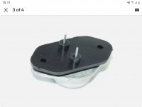
I intend to use two flat back 0.3 C/W heat sinks - I have already assembled KRELL KSA-50 in a simmilar manner. This time I intend to make my own plastic plate instead of bushings between the board and heat sink to make connection more stable and rigid.
Winter is comming over here in Europe and this amplifier would be a welcome addition to my good-old fireplace.
Thanks OldDIY
, I do really appreciate your advice,I intend to use two flat back 0.3 C/W heat sinks - I have already assembled KRELL KSA-50 in a simmilar manner. This time I intend to make my own plastic plate instead of bushings between the board and heat sink to make connection more stable and rigid.
Winter is comming over here in Europe and this amplifier would be a welcome addition to my good-old fireplace.
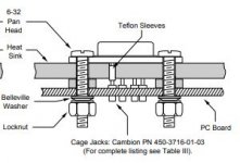
Not sure yet, but the material shouldn't be too rigid and yet not too flexible, something like teflon or PE should be just fine. Below is a drawing from Texas Instruments "mounting Considerations for TO-3 Packages". Instead of washers between the PC board and the heat sink I intend to use a plate perforated just at the locations of mounting and pin holes.Teflon? Fiberglass? Carbon?
For Krell I have used just ordinary TO-3 bushings but I'm not satisfied because the board can bend.
Attachments
Last edited:
Thanks Dude.Ebay item, vintage Philips Nos
That's exactly what I want.

EDIT:
Along with alumina TO-3 insulator this seems to be a perfect solution. Thansk again.

Last edited:
- Home
- Amplifiers
- Solid State
- JLH 10 Watt class A amplifier