What would happen if I feed this board (or the mini JHL previously mentioned) with bipolar -18v-0-(+18v)? I'm somehow committed to buy this one to feed the rest of my 5V unipolar DAC (TDA1387 + Amanero USB). I plan also to include an ADC symmetrizer board (DRV214) for XLR balanced outputs later, which nominally requires around 15VAC. That's why I'm pointing at higher voltages, to have a one-for-all power supply. As an alternative, using one 18VAC line of the bipolar transformer could solve it, but I'm afraid it could break the power balance used for the other applications in a noticeable way.
Otherwise, what power source would you use? I'm quite inexperienced on it, but linear is preferable due the almost analog simplicity of my DAC. The casing I will figure out later, but since I work with wood I'll try that route and not make a fire in the attempt")
Otherwise, what power source would you use? I'm quite inexperienced on it, but linear is preferable due the almost analog simplicity of my DAC. The casing I will figure out later, but since I work with wood I'll try that route and not make a fire in the attempt
The definitive Class A headphone amplifier using the split-phase drive principle is that shown on "The Class A Amplifier Site" originally published in Hi-Fi News in January 1979.
A number of JLH circuits there including this one were derived from copies of articles I scanned and sent to Geoff Moss decades ago. I still have the paper copies of these - some including the headphone amplifier with pcb layouts and performance specs.
The 1979 circuit is more advanced than the 1969 Class A. By then Linsley-Hood had moved on from capacitance multipliers, bootstrap collector loads, and output capacitor coupling.
Having built the 1969 and 1996 power amplifiers myself and listened to amplifiers like a Naim NAP 250 it is not hard to understand why.
Last edited:
I think JLH may have made a slight error in the design. His headphone amp can be found on Rod Elliott's site The Class-A Amplifier Site
JLH uses a 4.7k in the feedback loop and on the base of the driver device. Since that sees the base-emitter voltage of both the driver and lower output transistor the voltage drop is about 1.2V. Therefore the voltage drop will be a little more on the feedback resistor. Adding the base emitter voltage of the input transistor makes 1.8V plus a little due to bias currents.
Therefore, the two-diode bias voltage ought to be three diodes, I suggest, to get the output rail closer to zero. As it is it would currently be sitting high by a diode voltage or so.
I would not do that.
The original circuit had a tone control feed.
The final stage in this control was a Darlington MPSA65 (two diode junctions) serving as a common collector in company with a FET 2N5459.
The dc offset was via a 47k trimpot with a similar series parallel arrangement with different resistor values to the " A Change of Tone" follow up modification.
The bypass capacitors are tantalum 100uF 3 Volt rated.
Linsley-Hood published a high power amplifier with full dc coupling after the input capacitor in ETI in 1975. The input stage is a single input transistors as shown here.
The dc offset was managed by a two transistor constant current feed to the emitter of the input transistor. The arrangement was set up to provide thermal compensation to keep control of the output voltage.
In that regard two diodes 1N914 or 1N4148 in a heat environment would be a rough thermal match for two diode junctions in the MPSA65.
Last edited:
I'm not sure we are discussing the same circuit. My description was in regard of the one to be found on the TCAAS site which is hosted by Rod Elliott, and under JLH Headphone Amplifiers, circuit 1.
There is no tone control in it, and no means of adjusting the centre rail voltage.
What I wrote would, I suggest, still apply. Because the driver and lower NPN output transistor in the circuit I referenced amount to placing two Vbe's across the lower 4.7k base resistor, which is then replicated across the 4.7k feedback resistor. That therefore requires two Vbe's of compensation. Then, added to these is the third Vbe, the PNP base-emitter junction.
That requires three similar voltage drops to balance the junctions. So apart from providing a better balance, that should also provide a better thermal compensation.
I agree though that diodes are not the best match for thermal compensation. Transistors are always a better choice and not much different in price.
I did not see a Darlington device in the circuit I found, so I think that we must be thinking of different circuits. The two transistor ccs circuit you described is more like the updated 10W, not the headphone amp.
Rod Elliott pages JLH Headphone Amplifier
I have attached an image for reference purposes.
What JLH argued in the original article with the tone control was that a suitable input network forgetting the component values for the present would involve C1,R1, and R2.
The trick is to make the base voltages of Q5 and Q6 more negative than the emitters. Let's accept that applies with Q5.
The charge carriers flow from negative to positive ( opposite to the notion of current) thus once a headphone is connected Q5 will turn Q2 on electrons will flow as dc from earth via Q2 emitter to the positive rail if the lower circuit half is not providing enough electron flow.
It looks to me that the values of R1 and R2 were specified to allow a high input impedance for reasonable matching with signal sources including a relatively low value of 1uF for C1.
The voltage drop across R1 at 47k and R2 at 4k7 in series look questionable as sufficient to allow enough negative voltage on the base of Q4 if the reference is earth at 0 volts
That situation would change if the reference ground was below zero volts by the inclusion of D1 and D2.
If that doesn't do enough, since lower impedance reduces noise so one could reduce the value of R1 and perhaps R2 and increase those of C1 and C3.
With 3 diodes in place R1 could well need to be increased.
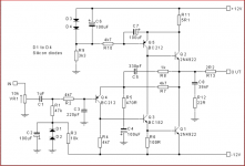
That was the circuit I was referring to (your post 7349). Before connecting a headphone, the output rail should be zero. Therefore, current will flow (I still use conventional current for general circuit descriptions) from the centre rail through R7 making the emitter of Q4 sit below zero. Since Q3 and Q1 require about 1.2V across R4, the voltage drop across R7 will be similar. Therefore, the emitter of Q4 has to be about -1.2V if the centre rail is at zero.
THerefore the base of Q4 has to be about -1.8V. I neglected the additional voltage drops across R1 and R2, which means we need -1.8V bias. That needs three diodes instead of just two (D1 and D2). Any voltage drop across R1 and R2 will raise the output voltage a little, so really it may need another diode - though I would recommend an adjustable bias of some description to set zero.
The quiescent current is set by Q5 whether or not a headphone is connected. The purpose of R10 and C7 is, I assume, to keep the current constant.
I would not design an amplifier which had a large offset voltage like this (as drawn) whether it is for a headphone or a loudspeaker.
Having seen your later post, 7350, it now makes sense that the Rod Elliott version needs the diode tweak, whereas the original has a tone control, as you mentioned. So it seems we were discussing different circuits.
As a general rule I don't think it is a good idea to try to incorporate a tone control in a power amp, though it was often done in the "old days".
Last edited:
Further Investigation
I did not build this circuit but waited for the RIAA circuit mentioned at the end of the article. This was able to drive high impedance headphones like the Sennheiser pair I had at the time.
Back on the main subject, I concede that your assertion about there being an issue with the circuit was correct.
For a rethink I adapted the .asc file for my a 1996 Class A power amplifier and tried I tried the three diode approach you mentioned. I found the circuit is finnicky and changing various component values was not making much difference.
In the end I reconfigured the dc offset adjustment and used the onboard library and Bob Cordells range of .models to source semi-conductors from what was available from these. I have not tidied component numbers.
In the new .asc file, R16 is shown as a 5k trimpot, the actual needs to drop around the same voltage as in a signal diode.
For that job 1N4148 might suffice or a collector to base shorted BC547B for that matter, however I think a trimpot will allow a range of adjustment to cover the inherent variations in semi-conductors of the same types etc.

Zero Zone. With a setting of 0.
https://aliexpress.ru/item/32810846...MI_7Pok6Lc7AIVjrGyCh3EtwVZEAEYASADEgKvRPD_BwE
Last edited:
Can I please call your attention to the latest post in my thread? I am trying to build an amp based on boards from China and have got something working but some questions and problems. I still have my 3 old boards (+ one broken) too.
I'm just starting out so not perfect with mounting heatsinks and stuff yet. I did a better job on the new boards which came with an L bracket for mounting a heatsink to the units.
Help with Hood Class A board (mockup fail)
I'm just starting out so not perfect with mounting heatsinks and stuff yet. I did a better job on the new boards which came with an L bracket for mounting a heatsink to the units.
Help with Hood Class A board (mockup fail)
quick note - the boards I recently bought say in the listing that they take DC but I don't see how and the board is marked for AC only. The other similar boards I linked are AC only. Please do your homework before purchase (unlike me!)I have built an amp prototype based on 2 1969 boards which are specced at 25w Class A each. The boards are currently listed on ebay similar.
Assembeld Hood 1969 MJE15024/25 Class A power amp board 25W 2 CH amplifier | eBay
This is the one I bought - almost the same... one pair left too.
I have a couple of questions:
1) The seller (after the build) recommended 2kg of aluminium heatsinking for the pair of boards. My heatsinks are only about 230g each. I could double up on them, double up on them and have 50% more heatsink on 2 of the 4 heatsinks, and probably try and use a fan to help with heat dissipation. Any thoughts on this? Is it going to be safe using the boards with just 460g - 900g Alu and a fan?
2) The transformer toroid I am using seems under spec. I am using an equivalent of 323-022 from this page:
Toroidal Transformer 80VA 0 - 22, 0 - 22 Transformers - Mains Toroidal
Obviously I am not getting the full 25w per channel with only 22v but I didn't realise enough that the toroid is only specced for 80w. I think I might be drawing more. Any way to be sure?
Any suggestions for alternative transformer for the pair of boards, or maybe 2 transformers?
The sound is very nice, rich, deep bass, controlled treble and a lot of body. It compares very well to the 60s Class AB Harmon Kardon A500 valve amp that I have (but is out of service at the moment). At least as good I would say - so I am pleased.
I have only tested the amp for up to an hour at a time before unplugging due to heat at the moment with 2 230g heatsinks (two of 200mm*69*37mm alu). They get pretty hot after this time, somewhat uncomfortable to touch. Unlikely to be over 100c
I do have a multimeter and an IR temp gun somewhere.
Last edited:
Newbie (Novichok
I am indeed a newbie but I have a load of amps to repair at home and a fair budget to learn amplifiers and electronics (and time)
Your comments on max safe temperature, heatsink size or weight required, whether I really have to use 18VAC on a board specced for 37VAC, etc would be appreciated in my thread or here
- Home
- Amplifiers
- Solid State
- JLH 10 Watt class A amplifier