I wouldn't say that swapping 4 transistors is a rebuild of the amp. Bought this amp just to see how good it was and thought about swapping the transistors and signal capasitors before I even decided to buy it.
About the sanken 3264 I looked at those for my other amp back in 2008 but the the project got forgotten along the way [emoji3] still Mj15003 in that one. Wierd, are you using original transistors in the rest of the amp?
Sent from my iPad using Tapatalk
About the sanken 3264 I looked at those for my other amp back in 2008 but the the project got forgotten along the way [emoji3] still Mj15003 in that one. Wierd, are you using original transistors in the rest of the amp?
Sent from my iPad using Tapatalk
Nice ") Is the rest of the circuit as the org. schema or are there resistors or capasitors that also need to be changed? I'm a bit interested in this particular circuit because I read an article many years ago in an norweian audio magazine. Someone from the magazine was visiting a guy at home to review his stereo. His amp was the JLH 10w but with a sanken on the output. The reporter was impressed by the amp. Since then I never could quite forget about it
Is the rest of the circuit as the org. schema or are there resistors or capasitors that also need to be changed? I'm a bit interested in this particular circuit because I read an article many years ago in an norweian audio magazine. Someone from the magazine was visiting a guy at home to review his stereo. His amp was the JLH 10w but with a sanken on the output. The reporter was impressed by the amp. Since then I never could quite forget about it
Is the rest of the circuit as the org. schema or are there resistors or capasitors that also need to be changed? I'm a bit interested in this particular circuit because I read an article many years ago in an norweian audio magazine. Someone from the magazine was visiting a guy at home to review his stereo. His amp was the JLH 10w but with a sanken on the output. The reporter was impressed by the amp. Since then I never could quite forget about it No, i follow the original schema.
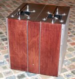
The inputcap is a (expensive) audionote copperfoil.
The psu is also old design.
Trafo 160 VA-15.000uf - coil (5mH)- 15.000uf- R 0.1-30.000uf.
Current is 1,8 A by ca. 30V.
The trafo is 24V ringkern.
The whole upset is for a single canal.
I know it is maybe a little overconstructed.
But it hard to find a better (sounding) amp when low power (ca.12 W) is enouch.
Nice
Linsley-Hood designed this amplifier for use with output transistors with a transition frequency of 4MHz. The stability margin with such devices is such there is no need for additional capacitors in the circuit. The choice of a 4MHz output device is to effect the dominant pole in the loop feedback characteristics - this in being the last link in the forward conduction chain.
The preceding transistors will amplify to much higher frequencies and substituting a 60MHz output will move the dominant pole to a much higher frequency. Some have tried this with 30MHz devices which ended up with the need to add a lead compensation capacitor in the feedback network.
The problem with this is there is a direct route via the lead capacitor for r.f. to enter the loop via the back door. To prevent that a buffer coil and zobel network safeguard could be used - but why go there if the circuit works properly as designed.
An approach to take with the outputs is to buy a number of devices - select the ones with the highest current gain and match them in pairs accordingly. You can use 2N3055, MJ15003, MJ21194 - commonly available 2N3055's will be epitaxial types.
In Class A the outputs operate under constant current conditions which makes the slowest devices easily fast enough since there is no need to switch on and off on opposite cycle swings.
Compare this with transistor switching delays in Class B due to the need to remove charges stored charges in the transistor base region.
A 60MHz transistor will have faster switching characteristics in a Class B circuit - the reason why 30 MHz and 60 MHz have been evolved.
There is no sense in comparing Apples with Bananas.
I will [emoji4] But first I'm gonna change the input and output cap.
Sent from my iPhone using Tapatalk
60 MHz is within the radio frequency range - with communications or other services possibly operating in this frequency band that raises the issues of your system causing interference or picking up external transmissions.
There are strict rules and issues of compliance for commercial stereo equipment and radio equipment in most countries. You will have to make sure that what you are doing will not put you in a position of breaching any rules.
I had an experience with a build 35 years ago using 30 MHz output transistors - I thought it an improvement until I turned on the television when playing some music. I did not want a visit from the authorities who track interference sources and dismantled my project accordingly.
Member
Joined 2009
Paid Member
I wouldn't say that swapping 4 transistors is a rebuild of the amp.
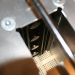
Well in my case it would be quite a large re-build. Not sure how easy it is to see from the photos but I have many output pairs (not much chance of beta-droop here) and each 2N3055H is riveted to the heatsink - yes, these were recovered from a pair of Acopian regulated power supplies. I'd have to dismantle the amp and drill out the rivets. I would not contemplate doing this unless the improvement is likely to be a revelation.
Oh, by the way, this is a mono-only amplifier - it's a tad larger than most of the 1969 builds I've see around here
Attachments
Last edited:
These amplifiers need far bigger heat sinks and power supplies than Linsley Hood indicated in the 1969 article. I built one of these with an 80 v.a. power transformer it lasted a couple of years before burning out. I replaced it with one having double the rating and it too suffered the same fate. It is well worth doing the job properly in the interests of reliability and not have this sort of worry even if the result is something relatively large in volume and weight.
Member
Joined 2009
Paid Member
Good to see a revived interest in J.L-H's amps. Toshiba 2SC5200s work well,only buy from reputable suppliers,as there are some fakes on the market. A visit to The Class A Amplifier (TCAAS),now hosted by Rod Elliot on his ESP website in Australia can prove most informative.I picked up that if the "bootstrap" drive is replaced with a Constant Current Source,there is an improvement in the sound quality,I found this to be the case.
Good to see a revived interest in J.L-H's amps. Toshiba 2SC5200s work well
You are relying heavily on SPICE test results and subjective assessment. SPICE tests only work if the transistor models are appropriate.
In view of posts by Mooly and John Ellis in December, I see objective testing as necessary to resolve this issue once and for all.
With subjective testing people are easily able to convince themselves that changes they make to systems will make a positive difference - I admit to having fallen into that trap myself.
With 30 MHz output transistors these extend the loop response so far upward in frequency where even small capacitance amounts in the load and connecting cable can excite resonances in a range where the loop gain is one or more - and - an element of the resonance in positive phase will be passed into the feedback line causing an overshoot.
That would make an amplifier sound brighter - perceived as an improvement - too much of this will make the listening experience less restful in the long run.
This possibility needs examination by square wave testing at 10 kHz into an 8R load with capacitors in parallel - testing a selection of values one at a time starting with the lowest. There should be no overshoots in the wave form seen on the oscilloscope.
There is no buffer coil, no zobel network, and no lag compensation scheme to mitigate against this. These are not necessary for complete stability with 2N3055's outputs as stated by Linsley-Hood.
The challenge for 30MHz transistor protagonists is to demonstrate the same degree of stability as above. If this condition is not met there is some work to do with the measures above and the resultant wave forms will not be as good as represented.
Hello all,
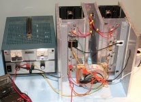
I just put together 2 JHL amps using eBay PCBs for the 2003 dual supply version. I used MJ15024 for outputs with 2 24V 4A commercial open frame linear supplies. I had to limit the bias to 1A because the heatsinks I have on hand are too small. They sound great though, driving my Martin Logans well until they clip. Great detail and even good bass, even with low power.
Now I am going to built it properly with large heatsinks and such. But what to do with power supplies? My linear power supplies run really hot too and I will have to cool them somehow. On top, I think I need to up the bias to 4A or so to avoid clipping before good volume is reached. I am thinking one of these 24V 10A switching power supplies or similar. What do you think?
CNC Servo Step Motor Driver AC to DC Power Supply 36V 10A Adjust 5V to 40V 360W | eBay
Thanks in advance!
DO consider how much power you REALLY need (as I have posted before),dissipating heat is not only a nuisance,but requires even more expensive heatsinks.
Hello Alan,
You are absolutely right but I know the amp was clipping rather badly and I figure better to make a big step increase rather than taking baby steps and never getting there.
Would these SMPS work or would they be too noisy?
Ray
I think cheap SMPS will have switching noise. For class A high current there won't be cost savings compared to linear toroidal trafo and cap bank. By the time you add enough filtering to SMPS costs about same or more and may not be as quiet. Some supplies though are very quiet - like Abletec 53v. However that unit is not for class A as it is 1.5amps continuous.
In US, Antek has very reasonable prices for large power transformers.
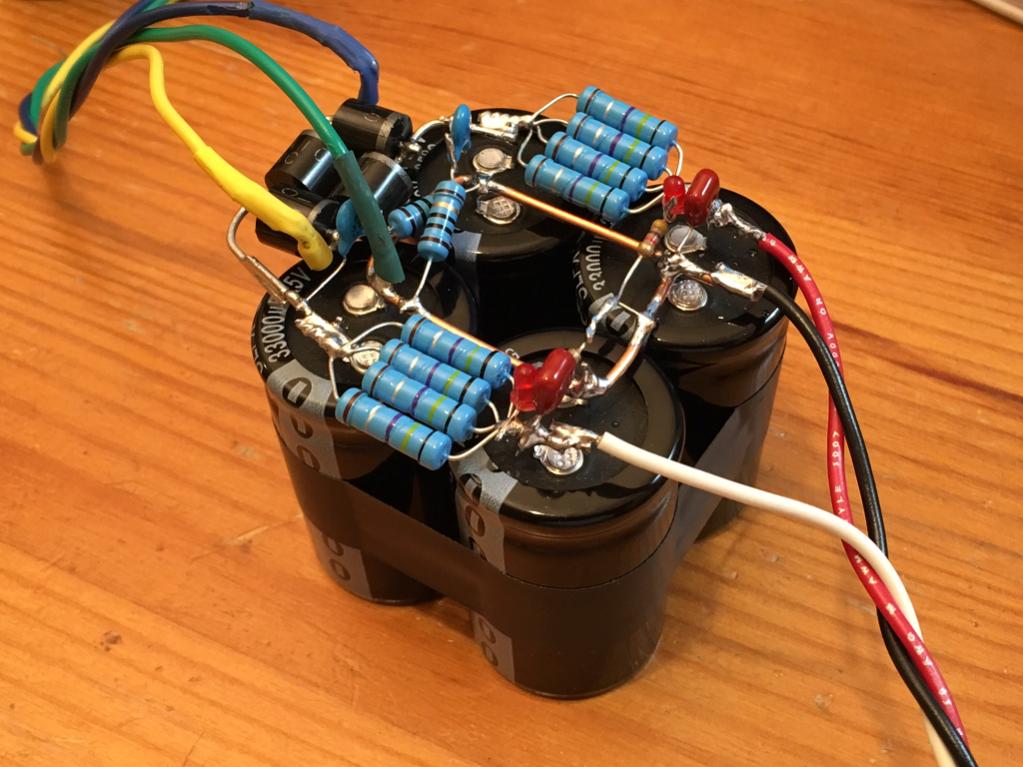
Btw, CRC PSU's are not hard to make and don't need a PCB. In fact, I think P2P will be as compact as you can possibly get it. Here is a rectifier/RF snubber CRC with 33mF x 4 and 4x0.47R resistors per rail. Look how small you can make it and cost is really just price of caps. Rest of parts are peanuts.
In US, Antek has very reasonable prices for large power transformers.
Btw, CRC PSU's are not hard to make and don't need a PCB. In fact, I think P2P will be as compact as you can possibly get it. Here is a rectifier/RF snubber CRC with 33mF x 4 and 4x0.47R resistors per rail. Look how small you can make it and cost is really just price of caps. Rest of parts are peanuts.
Last edited:
- Home
- Amplifiers
- Solid State
- JLH 10 Watt class A amplifier