Member
Joined 2009
Paid Member
In the context of a Class A system 2N3055 transistors are quite up to the job.
+1
However, they do suffer from beta droop and in my view benefit from paralleling.
http://www.diyaudio.com/forums/solid-state/268846-tgm9-my-version-jlh-69-class-amplifier.html
+1
However, they do suffer from beta droop and in my view benefit from paralleling.
http://www.diyaudio.com/forums/solid-state/268846-tgm9-my-version-jlh-69-class-amplifier.html
Doubling up on output devices would split the load and enable 2N3055's to work in a lower current region where the current gain would be higher. I don't see any advantages in having 8 pairs in each output half other than making use of available spare parts. You might include some low value emitter resistors to aid load sharing.
The approach taken by Hood was to substitute a better device in the phase splitter to boost the drive current and increase the overall loop gain.
Transistor datasheets refer to "current gain" where with power devices it can be seen graphically this falls with progressive current increases. At high currents the gain can be very low which has serious implications in high power (Class AB) amplifier design characterized by designers as "beta droop". I think the term should be limited to that context.
With a 10 watt Class A amplifier the term "beta droop" might suggest to some a problem of a mountain rather than a molehill.
geoff moss design 2005
Hi
I'm trying together geoffs design from 2005. 15 watts.
As I understand it I can skip Q1a and Q2a, these I can use to make the high power circuit?
I've taken steps and trippel checked the transistors to get them in the right place.
I can not remove DC off the speaker out. does not matter how much I turn the pots. 25turns so I can really have a good time of it.
Q2 certainy gets hot, but Q1 keeps hot.
Output transistors is 2sc5200 and I'm using 2sa970 for iq and input, bd139 and 140 for driver.
I've build three of these now and same problem with everyone. Even checked the transistors ... new ones and still the same. checked each solderpoint (tripple and quadruple that).
Anyone throw me a bone here? I've done a few of the penultimate circuit, but these seem to be working just fine with no problems
Passive tone controls are OK but lossy which means you either need gain before or after them to make up the loss.
Passive tone controls seem to be very popular in guitar amps and diy pedals ( stomp boxes ) Not quite sure what the rationale is for this preference as like Mooly said you need to make up the gain lost in the passive network. There seem to be some rather esoteric ideas about what effects certain circuit configurations and component choices have on the reproduced sound of guitar signal chains. I was a bass player though and in general I reckon we're more pragmatic than guitar players!

Not quite sure what the rationale is for this preference ..... I was a bass player though and in general I reckon we're more pragmatic than guitar players!
Tradition. Plus it's cheap.
Also "normal" guitar tone stacks are anything but flat when you think they should be. Plus there's usually interaction between the knobs. The Brand-X "sound" is partially associated with their historical tone-stack bumps and wiggles.
Bass players tend to use bandaxall tone stacks. Which actually are flat when you think they should be. Pragmatic.
Hi
I'm trying together geoffs design from 2005. 15 watts.
As I understand it I can skip Q1a and Q2a, these I can use to make the high power circuit?
I've taken steps and trippel checked the transistors to get them in the right place.
I can not remove DC off the speaker out. does not matter how much I turn the pots. 25turns so I can really have a good time of it.
Q2 certainy gets hot, but Q1 keeps hot.
Output transistors is 2sc5200 and I'm using 2sa970 for iq and input, bd139 and 140 for driver.
I've build three of these now and same problem with everyone. Even checked the transistors ... new ones and still the same. checked each solderpoint (tripple and quadruple that).
Anyone throw me a bone here? I've done a few of the penultimate circuit, but these seem to be working just fine with no problems
The 2sa970 has a different lead configuration than BC560. It is not a direct replacement and you would need to orient the transistor body and transpose the leads to fit a board where the overlay indicates a BC560.
In previous posts I made the point that 2N3055 is good enough for this amplifier. It is because of the limited frequency response fT of 2 MHz which ensures loop gain has reduced to less than one before the phase reaches 180 degrees - a condition that is necessary to ensure stability.
Using 2SC5200 would be like driving a car that can go faster but does not have the brakes to match.
Hello . i am thinking of making the first version of JLH class A amplifier 1969.It will be my first class A amplifier. What transistor should i choose for TR3 (2N697,2N1613) and for TR1,TR2 (MJ480) ?
For TR1,TR2 i have TIP3055,MJL21194,BD249C.
For TR3 i have MJE340,BD139,2N5551,2N2219,2SD669,TIP31
For TR1,TR2 i have TIP3055,MJL21194,BD249C.
For TR3 i have MJE340,BD139,2N5551,2N2219,2SD669,TIP31
Attachments
This might help: The Class-A Amplifier Site - Transistor Substitutes
MJL21194 would be fine for Tr1/Tr2.
BD139 should be fine for Tr3, but ideally selected for highest Hfe (unless you can get the BD139-16 version)
/U.
MJL21194 would be fine for Tr1/Tr2.
BD139 should be fine for Tr3, but ideally selected for highest Hfe (unless you can get the BD139-16 version)
/U.
can anyone suggest a high hfe alternative to bd139?This might help: The Class-A Amplifier Site - Transistor Substitutes
MJL21194 would be fine for Tr1/Tr2.
BD139 should be fine for Tr3, but ideally selected for highest Hfe (unless you can get the BD139-16 version)
/U.
2SC3902.
Actually, before Philips sold off NXP the last update to their BD139 showed that the minimum gain was now the -16 group (63 min, 100 typ.) All the ST and ON Semi devices I have are ~100 at 100mA although not all are graded ~16. NXP do not appear to sell the BD139 any longer.
John
Actually, before Philips sold off NXP the last update to their BD139 showed that the minimum gain was now the -16 group (63 min, 100 typ.) All the ST and ON Semi devices I have are ~100 at 100mA although not all are graded ~16. NXP do not appear to sell the BD139 any longer.
John
Found Yet Another Article on the JLH, using some simple CLC power supplies
Tom's Hacks: Class A contender no.1 - JLH 1969
Tom's Hacks: Class A contender no.1 - JLH 1969
Member
Joined 2009
Paid Member
I also used CLC and found the amplifier plenty quiet enough.
http://www.diyaudio.com/forums/solid-state/268846-tgm9-my-version-jlh-69-class-amplifier.html
http://www.diyaudio.com/forums/solid-state/268846-tgm9-my-version-jlh-69-class-amplifier.html
Thanks, trying to get links to all the projects in here as a kick off point. Just got a 400VA transformer as step one for a LCRC powersupply.I also used CLC and found the amplifier plenty quiet enough.
Component change?
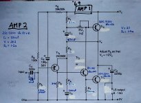
Many years ago I built 2 x JLH '69 monoblocs. A correspondent on one site suggested (in order to improve HF response) certain component changes as shown in the diagram. You will notice that CI differ in value, this must have been my error when constructing. I invite any criticisms. The PSUs are the original '69 stabilised ones.
These are driving Quad 57s (in a small room) and sound very good.
Attachments
Simulation results show a worthwhile fall in distortion from using modern output devices on the original design.
Your changes seem to indicate a further reduction in distortion but also a small but significant peak in the response at extreme HF (approaching 10MHz or so) where there was none before. As ever, you need to fully evaluate the changes, not just as a quick simulation but also when driving real loads... and the ESL is one load that demands a stable and well behaved amp.
My advice... stick to the original concept with the proviso that changing to modern outputs could be worthwhile.
- Home
- Amplifiers
- Solid State
- JLH 10 Watt class A amplifier