Can anyone suggest a way of adding a 'Master Volume' control - after the R3, R4, C3 combo on the JLH '69 schem?
I've got the amp running off +9V as a small guitar amp and I'm using a pot at R4 as a crude Gain control but I'd like control over the final volume so I can crank the gain - but reduce the volume at the output.
I tried just running a pot as a voltage divider between the output cap and the speaker but that's not working too well.
Thanks!
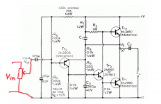
None of those will work. You need a pot at the input to control gain. Altering R4 does alter gain but it alters a whole lot of other stuff too as it it alters the feedback factor.
Yeah - kind of expected that might be the case. Worth a try though - thanks.
Member
Joined 2009
Paid Member
In the spirit of DIY - why not add a gain adjust into the feedback network. I Since it is for a guitar amp some of the consequences may not be an issue.
Things to consider
- don't reduce the gain too far as this implies increased negative feedback which may make the amplifier unstable. You can amerliorate this with a small capacitor across base-collector of TR3 (try 100p npo ceramic).
- you may want to reduce or otherwise change R3 to give a different range of adjustment from your variable R4
In the spirit of DIY - why not add a gain adjust into the feedback network. I Since it is for a guitar amp some of the consequences may not be an issue.
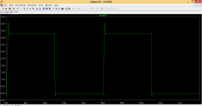
I must admit that just trying it in simulation and its acceptable up to a point. Making R4 a 22k with a 100 ohm series limiter and it does work.
This is with R4 at 22k and a 25k squarewave

Attachments
Hi
A volume control in the feedback loop is generally not a good idea. It can change the stability of the amplifier. I have however used this as a balance trim in the past, but the variation in gain was limited and within the stability range.
If you use a pot in the output on the speaker, it will have to be something like 10 ohms 10W rating and at full volume could overload the amplifier (total load=4 to 5 ohms -OK if the amp can drive this, but the JLH targets a particular impedance).
Unfortunately a standard volume control on the input may not be a good idea either. The problem is that at mid-turn (anything from say 10% to 90%) the impedance is high (say 10k-ish for a 22k pot) and this can increase the distortion in the amplifier, change the frequency response (down) or even cause instability again (by changing the frequency response of the input stage).
However for the JLH design used as a guitar amp this may not be a problem in this case.
What I would suggest in general is to use a 1-transistor buffer stage (emitter follower)- or a FET buffer - with an input control so that the impedance to the power amp. stays more or less low, under 1k at least.
John
Dear Thijs,
2N3055's are very old design, yes. And they exhibit poor linearity, I cann't agree whith you. On my desk, the Motorola Power Data Book, I can see : Typical Dc current gain 150 @ 0.25 A , 80 @ 1 A , 50 @ 2 A. This causes important, audible harmonic distortion, at all frequencies.
The low current-gain-bandwith product (2 Mhz) causes very unpleasant intermodulation distortion at high frequencies.
.
Hi, was just reading through this thread from the beginning and came across this post. I understand the first part about gain non-linearity, can anyone explain how low GBW causes intermodulation distortion? Sorry if this deviates from the current topic, I was unsure where to place this question.
With thanks, Gordon.
I'm not sure there is a simple answer one size answer to that. As the gain of the output devices at hf fall then the output impedance of the amp tends to rise. That effect is one cause of IM distortion rising. These effects are noticeable particularly when testing open loop gain.
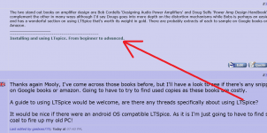
The two stand out books on amplifier design are Bob Cordells 'Designing Audio Power Amplifiers' and Doug Selfs 'Power Amp Design Handbook'. Both complement the other in many ways although I'd say Dougs goes into more depth on the distortion mechanisms while Bobs is perhaps an easier read and has a wonderful section on using LTSpice that's worth its weight in gold. There are probably extracts of each to sample on Google books or Amazon.
Thanks again Mooly, I've come across those books before, but I'll have a look to see if there's any snippets on Google books or amazon. Going to have to try to find used copies as these books are costly.
A guide to using LTSpice would be welcome, are there any threads specifically about using LTSpice?
It would be nice if there were an android OS compatible LTSpice. As it is I'm just going to have to find some coal to fire up my old PC!
A guide to using LTSpice would be welcome, are there any threads specifically about using LTSpice?
It would be nice if there were an android OS compatible LTSpice. As it is I'm just going to have to find some coal to fire up my old PC!
Last edited:
A guide to using LTSpice would be welcome, are there any threads specifically about using LTSpice?
Err... yes
Attachments
Err... yes
DOH!!!!!
But honestly, I didn't realize it was a link, dunderheid that I am!
I have LTSpice on my old coal fired PC, but never got much further than using it for schematic capture. Running simulations should help prevent me from needlessly murdering some nice transistors. I look forward to reading the thread.
Thanks again,
Gordon.
Last edited:
.
Hi, was just reading through this thread from the beginning and came across this post. I understand the first part about gain non-linearity, can anyone explain how low GBW causes intermodulation distortion? Sorry if this deviates from the current topic, I was unsure where to place this question.
With thanks, Gordon.
In the case of 2N3055 transistors in a Class A unity gain output stage the voltage gain will remain at near enough to one up to the maximum frequency obtainable from the device - somewhere around 2 MHz.
The choice of these transistors is deliberate since the frequency characteristics set the dominant pole for the entire circuit and avoid the need for slew rate limiting compensation capacitors around the voltage amplification stage.
This is an unusual approach but the amplifier is simple with limited loop gain which works but which puts it at odds with the conventions applicable to Class AB designs.
There the need for fast switches is met by 50 MHz power transistor types. Nonetheless such output stages suffer due to stored charge effects in the device bases which curtail their response at high frequency - entailing a corresponding variation in the angle of the feedback signal.
This implies that voltage gain must be reduced to one before the feedback signal reaches 180 degrees or more (where it will oscillate). That can happen at perhaps as low as a tenth of the nominal FT value of 50 MHz.
Even with two pole compensation it may be necessary in a worthy design employing the latest design strategies and devices, to reduce the loop gain to one around 1 MHz to provide adequate phase margin. I am basing these observations on a project published by Silicon Chip magazine available as a kit from Jaycar and Altronics in Australia.
In the context of a Class A system 2N3055 transistors are quite up to the job.
Last edited:
How?.................... never got much further than using it for schematic capture..................
Can you explain how to take a sch and insert it into LTspice?
How?
Can you explain how to take a sch and insert it into LTspice?
Iam not aware of any method to do this automatically, if that's what you mean. I was talking about using the program (ltspice) for manually drafting diagrams, as an alternative to, in my case, messy drawings!
If you are looking for instruction on how to do that and MUCH MUCH MORE! I refer you to Mooly's excellent tutorial;
http://www.diyaudio.com/forums/software-tools/260627-installing-using-ltspice-beginner-advanced.html
Gordon.
Hope this isn't too OT for this thread…
I mentioned recently I was looking at quick and dirty ways of adding a passive master volume to a version of the JLH '69 I've built as a little guitar amp. The advice I got was basically - 'do it properly'
So I thought I'd also look at inserting a passive tone control (either a Baxandall or the classic 'FVM' design), followed by a passive attenuator as a volume control in-between the high impedance FET input I already have running and the input of the amp (Tr4 on the '69 schematic) - like so:

Stuff in blue is to be built - does that look feasible?
Specifically…
What value cap would you suggest to AC-couple the output of the FET?
Would you swap the order of the Tone and Master Volume?
Do I need the extra BJT buffer for biasing before Tr4>
Anything else?
Thanks - appreciated.
I mentioned recently I was looking at quick and dirty ways of adding a passive master volume to a version of the JLH '69 I've built as a little guitar amp. The advice I got was basically - 'do it properly'
So I thought I'd also look at inserting a passive tone control (either a Baxandall or the classic 'FVM' design), followed by a passive attenuator as a volume control in-between the high impedance FET input I already have running and the input of the amp (Tr4 on the '69 schematic) - like so:
Stuff in blue is to be built - does that look feasible?
Specifically…
What value cap would you suggest to AC-couple the output of the FET?
Would you swap the order of the Tone and Master Volume?
Do I need the extra BJT buffer for biasing before Tr4>
Anything else?
Thanks - appreciated.
Passive tone controls are OK but lossy which means you either need gain before or after them to make up the loss.
Not sure what your 4700uf cap is at the front. That's way to big for any coupling cap in small signal stages. FET preamp need to be able to drive the passive tone network OK. Has it got that drive ability ? It might be best to swap positions of the volume control and emitter follower. That way the volume control attenuates any noise from that stage.
Always many ways of doing things, no one size fits all.
- Home
- Amplifiers
- Solid State
- JLH 10 Watt class A amplifier