Jay, I discarded the Pass designs the day I built my first MOSFET based source follower pure SE class-A amplifier(the project-83 MOSFET power follower in ESP site coupled with DOZ preamplifier) which sounds marvelous. What I believe now is that the pass amps are simply not my cup of tea. You can not convince me otherwise no matter what you say, do or suggest, until the day comes on which I get my hands on a $200 fullrange with 96dB sensitivity.
I decide the "best" ONLY after building an amp myself and listeing to it. So the amps I consider to be good or bad have already been built by myself. BUT, I will never suggest you anything I built and found to be good because I don't consider other's "best" as something suitable(let alone be best) for me.
Jay, how do you focus on the "best" only and know that an amp is "best" before building it? Just by looking at the design? Or the simulation results? Or because Stereophile said it is?
Please stop suggesting anything other than JLH variations, like the CFP type phase splitter suggested above, this is the JLH 10 watt thread. PM me if you have to suggest anything else.
No, actually I'm not trying to suggest anything. I'm not a fan of Pass amps either.
But yes, it is easy to know the sound of an amp from the schema. That's why I discarded Pass amps. But it doesn't prevent me from building them, because I can try different (better) devices and shunt power supplies.
You seem to like details in the music. The source follower is suitable for this as the capacitance is not really a big issue. You have compared the P-83 which is a S-follower with Zen amps which are D-followers.
The source follower is also my preference. But now we have "damping factor" issue. My current approach to this is using push pull topology. Something like the Tumos, Moskido and others (And a paralleled output of course). But if someday I got a very good Mosfet as used by VladimirK, of course I will re-try many "old" designs including Pass designs.
I'm now comparing VFET (with its suitable topology) with LATFET (with it's own suitable topology) and see which one win the race. And I still have a little curiosity with bipolar amps. My intuition told me that the JLH with plenty of paralleled faster devices should sound acceptable to my ears.
Last edited:
With mosfet, paralleling output device means higher capacitance, which is a drawback. But with bipolar I want more devices
OK, Jay, that is your point of view. However, audiophiles usually consider every splitting of the signal path as a forbidden approach. I like your preference of high fT BJT transistors at the output. Please, tell which set of parameters (Pd, fT, Vce, Ic etc.) you would dream about a single output BJT. Could be, your dream can become a reality.
Last edited:
Homemodder,
Which book is it where he states using a CFP for the phase splitter?
I have Audio Electronics and The Art of Linear Electronics and I've not managed to find this reference yet.
Thats the one, there is a section dedicated on phase splitters, I think so anyway. I read the 2nd edition about 2 years back but it should be in the first as well.
From basic electronic principles it should be clear why a CFP is superior anyway, keep in mind that the phase splitter is in principle a emitter follower and the ways one improves those.
OK, Jay, that is your point of view. However, audiophiles usually consider every splitting of the signal path as a forbidden approach.
The problem is not in the splitting but in the regrouping after splitting
For example, see attachment!But like many things else, it is about compromises: how much to gain and how much to loose. In general, imo good sound comes from 2 things: internally from the amp itself and externally from its ability to synergy with the speaker.
What is the common weakest link in an audio system? The speaker. What is your preference/criteria for ideal loudspeaker? A 3-way that can play complex music, piano, etc. So from this "ideal speaker" we can imagine at least 10" woofer, with impedance that can go below 5 Ohm, often with sensitivity of less than 85dB. Then comes the important requirement for an amplifier with sufficient "damping factor". This is important for a system to sound good especially in bass department.
For exactly the above reason I gave up pure single ended amps, and chosen the theoretically less good topology: push-pull. But I don't want to give up everything. I still want a class-A. Mostly source follower due to common weaknesses with mosfets on hand, and other good things for being pure current gain output stage.
Paralleling output devices will improve speaker handling, will thus improve bass quality and others. This is what to gain with paralleling.
I like your preference of high fT BJT transistors at the output. Please, tell which set of parameters (Pd, fT, Vce, Ic etc.) you would dream about a single output BJT. Could be, your dream can become a reality.
I don't have many (critical) experience with bipolar amps. I just know that I don't like their typical sound. The best bipolar amp that I have heard in the past was from the Sanken ring emitter 2SC2922. It is a good coincident that it has 50MHz of fT.
From my understanding of the typical sound of bipolar amp, and from my (limited) understanding of how circuits work, I guess that the real issue with bipolar sound is linearity. Others are only excess, or causes.
If I had to dream of an ideal BJT, it is still not ideal because it will depend on the whole circuit to make a linear amp. Bipolar amp designers (and transistor designers) must know better what are the biggest challenge in making the amp (or transistor) linear, without having to introduce other issues such as using global feedback!! (somebody please tell me where and what to look for).
As for my interest with parallel output in bipolar amps, I still don't have no idea how to relate this with linearity. But if the amp load is not a pure resistor (i.e. speakers) the parallel device may improve linearity???
Attachments
Member
Joined 2009
Paid Member
A-ha! Eight transistors at the output of the JLH! That's what I have been thinking to build (at least 0.65mA each). How/why do you come up with that circuit?
I think if we see the JLH as a single ended collector "follower", the CFP splitter should do no harm but good, even if the distortion spectrum is different. I will build this hopefully within next month
I happen to have some heatsinks from an old power supply, each heatsink already has four 2N3055's riveted (yes, riveted) to it. I figure I should use them to build a JLH. I have 4 of these heatsinks, so I will have 4 output pairs per channel for stereo. I have most of the chassis made up now, and a toroid for the power supply (dual 18V a.c. secondaries) but as yet I didn't get around to building it.
I also like the look of the CFP splitter - it improves the 'drive' to those hungry output devices and further improves linearity at large signal swings.
By the way, I agree with Vladimirk - I do find it hard to find good source material. I don't have any vinyl, maybe that should change.
Jay, I think BJTs are VERY non-linear at small base (and respectively collector) currents. At high currents (static measurements) they become pretty linear with respect to base-emitter voltage. Why not to think about class A with operation point at more linear range, few amps lets say?
There are many BJTs for RF applications, with fT around 0,5GHz, Ic 10...20A, Pd 100...150W, Vce0 36...75V. If the rest of design deserves such a BJT, final sound will be impressive.
There are many BJTs for RF applications, with fT around 0,5GHz, Ic 10...20A, Pd 100...150W, Vce0 36...75V. If the rest of design deserves such a BJT, final sound will be impressive.
The problem is not in the splitting but in the regrouping after splitting
But like many things else, it is about compromises: how much to gain and how much to loose. In general, imo good sound comes from 2 things: internally from the amp itself and externally from its ability to synergy with the speaker.
What is the common weakest link in an audio system? The speaker. What is your preference/criteria for ideal loudspeaker? A 3-way that can play complex music, piano, etc. So from this "ideal speaker" we can imagine at least 10" woofer, with impedance that can go below 5 Ohm, often with sensitivity of less than 85dB. Then comes the important requirement for an amplifier with sufficient "damping factor". This is important for a system to sound good especially in bass department.
For exactly the above reason I gave up pure single ended amps, and chosen the theoretically less good topology: push-pull. But I don't want to give up everything. I still want a class-A. Mostly source follower due to common weaknesses with mosfets on hand, and other good things for being pure current gain output stage.
Paralleling output devices will improve speaker handling, will thus improve bass quality and others. This is what to gain with paralleling.
I don't have many (critical) experience with bipolar amps. I just know that I don't like their typical sound. The best bipolar amp that I have heard in the past was from the Sanken ring emitter 2SC2922. It is a good coincident that it has 50MHz of fT.
From my understanding of the typical sound of bipolar amp, and from my (limited) understanding of how circuits work, I guess that the real issue with bipolar sound is linearity. Others are only excess, or causes.
If I had to dream of an ideal BJT, it is still not ideal because it will depend on the whole circuit to make a linear amp. Bipolar amp designers (and transistor designers) must know better what are the biggest challenge in making the amp (or transistor) linear, without having to introduce other issues such as using global feedback!! (somebody please tell me where and what to look for).
As for my interest with parallel output in bipolar amps, I still don't have no idea how to relate this with linearity. But if the amp load is not a pure resistor (i.e. speakers) the parallel device may improve linearity???
Theres much to correct in this post, I think you should try get some books on electronics and get the facts and principles straight.
BJTs are in fact far superior linearity wise compaired to mosfets. They have much higher transconductance so to make a comparison between the two the bjt must be degenerated to the same transconductance or in short gm of the mosfet. The best part in this is that even at the same transconductance the BJT still shows better linearity. Throw this misguided theory of yours in the waste bin where it belongs. The mosfet have some positive attributes but they are not related to linearity. Consult Nelson Pass seeing that you like his designs, in fact in one of his papers he explains this and why he only uses them in class A.
Secondly when you take into account the high gate capacitance of mosfets youll find that in practice their ft is not much better than BJT,s. For them to be able to achieve those high speeds they need to be driven by followers to overcome those capacitances.
The paralleling of mosfets is not such a big problem, yes its true the capacitance increases but youre forgetting the effect the increase in transconductance will have on the circuit when used as followers. So in all the outcome is not so negative as you might think. Once again you could consult Pass.
Theres much to correct in this post, I think you should try get some books on electronics and get the facts and principles straight.
Don't focus on the misguided theory, but focus on the need for explaining the phenomena. I have tried to look beyond what I have read about theory. Explain something that I have never heard or read.
Consult Nelson Pass seeing that you like his designs, in fact in one of his papers he explains this and why he only uses them in class A.
Yes, I have read all his pdfs. But I'm not a fan of him or his designs. I prefer reading John Broskie.
Secondly when you take into account the high gate capacitance of mosfets youll find that in practice their ft is not much better than BJT,s. For them to be able to achieve those high speeds they need to be driven by followers to overcome those capacitances.
I have built many simplified gain stage of latfet amps, such as that double LTP suggested by Hitachi. The premise is that mosfet doesn't need complex drive that the number of stage can be reduced. DISAGREE. Such amps do not impress me. I need extra emitter follower to drive the mosfet. This is from practical experience, not theory. Why the hell so many experts who know the theory do not act based on it?
The paralleling of mosfets is not such a big problem, yes its true the capacitance increases but youre forgetting the effect the increase in transconductance will have on the circuit when used as followers. So in all the outcome is not so negative as you might think. Once again you could consult Pass.
Actually I don't think that the final outcome regarding added capacitance (versus added transconductance that will lower the Zout) is that negative. Practice is more important than theory to me, because theory can be misunderstood while ears, I believe in mine. The Aleph 2 is the (practical) proof. Actually I can TRY to use theory to explain that, but why not expect any expert to do that instead of them explaining non-precise words we all can read somewhere.
Don't focus on the misguided theory, but focus on the need for explaining the phenomena. I have tried to look beyond what I have read about theory. Explain something that I have never heard or read.
.
Misguided theory, phenomena........ ???
You believe in ufos and the fairy godmother too ??
Jay, I think BJTs are VERY non-linear at small base (and respectively collector) currents. At high currents (static measurements) they become pretty linear with respect to base-emitter voltage. Why not to think about class A with operation point at more linear range, few amps lets say?
"Few" amps?
Yes, I always pay attention to those pdf charts for every transistors that I own. May be transistor designer/manufacturers should co-operate more with audio industry and design transistors that is linear at practical operating conditions for most amplifiers.Wow, I have never seen/own such creatures.There are many BJTs for RF applications, with fT around 0,5GHz, Ic 10...20A, Pd 100...150W, Vce0 36...75V. If the rest of design deserves such a BJT, final sound will be impressive.
Misguided theory, phenomena........ ???
You believe in ufos and the fairy godmother too ??
No. I believe that ZenV4 and JLH sounds different. I believe that I don't like the typical sound of bipolar amps. I GUESS that this typical sound of bipolar amp is caused by linearity issue. You should be able to explain better, such as that it is just a voodoo. That would be a minimum expert answer
No. I believe that ZenV4 and JLH sounds different. I believe that I don't like the typical sound of bipolar amps. I GUESS that this typical sound of bipolar amp is caused by linearity issue. You should be able to explain better, such as that it is just a voodoo. That would be a minimum expert answer
Probably they do indeed. Ive already explained it, for proof youd need to get hold of some electronic lab equipment and you could verify the facts for yourself. I cannot do this for you. Mosfets are not more linear than BJTs.
Anyway enough voodoo for me for one day, Ill check later in the thread if someone does try the cfp mod to hear about the outcome.
I happen to have some heatsinks from an old power supply, each heatsink already has four 2N3055's riveted (yes, riveted) to it. I figure I should use them to build a JLH. I have 4 of these heatsinks, so I will have 4 output pairs per channel for stereo. I have most of the chassis made up now, and a toroid for the power supply (dual 18V a.c. secondaries) but as yet I didn't get around to building it.
I've build a JLH with 2N3055 (toshiba it was I believe) and dual 18V secondairies followed by a cap multiplier dropping some volts. Still the 2N3055's in one channel kept dying on me, even while the Iq wasn't very high. I came to the conclusion (actually a forum member suggested that) that they had to operate just outside their SOA. So I've replaced the 2N3055's with a different type of transistor and the dying was over.
My suggestion: build with lower rail voltage.
MArco
Mosfets are not more linear than BJTs.
Of course I have read your debates with others regarding which one is more linear. I OTOH never implied or been care if one is more linear or not than the other. Most debates are never ending because one or more has not the ability to read between the line, or to get the essence of what is being said.
I've build a JLH with 2N3055 (toshiba it was I believe) and dual 18V secondairies followed by a cap multiplier dropping some volts. Still the 2N3055's in one channel kept dying on me, even while the Iq wasn't very high. I came to the conclusion (actually a forum member suggested that) that they had to operate just outside their SOA. So I've replaced the 2N3055's with a different type of transistor and the dying was over.
My suggestion: build with lower rail voltage.
In my country power supplies are built using 2N3773. Many 3055 are fake. Some may be "genuine" but have lower Vcemax.
Wow, I have never seen/own such creatures.
I have managed to get some amount of NOS russian KP958A RF transistors, with Vceo=36V, Ic=10A (20A peak), hFE>5 at 100MHz, Pd=80W at 40 deg C at the case, all pins are isolated from the case, case and pins are gold plated.
For those who believe in their abilities and would contact me via personal mail, I could offer such parts, if somebody arrange buying around 10 of them (maybe a group buy). Actually this proposal is not for profit. For DIYers, having such parts, can arise new activity and stimulate some new personal discoveries.
Member
Joined 2009
Paid Member
Ill check later in the thread if someone does try the cfp mod to hear about the outcome.
I want to finish my JLH in the next few weeks (actually by end of March but nothing guarantees it will take a long time like setting a deadline...). Anyhow, I am seriously considering including a provision for the cfp phase splitter so I will be able to try this out. It's not a panacea, there are tradeoffs, primarily stability. I fear some Cdom will be required to tame the cfp. However, it does provide more OLG and I would like to trade this off for lower gain of the input device - using a lower collector load resistor than the standard 8k2 will allow more current through this device.
Hi Jay,
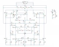
As you are planning to build a version soon I thought you may be interested / amused to see a balanced version I built in 2000 and enjoyed for a few years - I changed the feedback resistor values on the diagram for more inherent stability. The driver mosfet is a ZVN3310a and this combined with the i/p stage CCS greatly increases OLG and reduces HD.
I am aware some would say I ruined the concept by increasing OLG & adopting compensation, but I found these modifications pleasing and compared to other topologies this design still has a significant gain / phase advantage.
I'm sure I would do it differently if I were to do it again today - mainly reducing PSU voltage and increasing bias current. I would also be temped to do an mosfet o/p version which I have read good reports about.
mike
Attachments
Last edited:
Hi Jay,
As you are planning to build a version soon I thought you may be interested / amused to see a balanced version I built in 2000 and enjoyed for a few years - I changed the feedback resistor values on the diagram for more inherent stability. The driver mosfet is a ZVN3310a and this combined with the i/p stage CCS greatly increases OLG and reduces HD.
I'm sure I would do it differently if I were to do it again today - mainly reducing PSU voltage and increasing bias current. I would also be temped to do an mosfet o/p version which I have read good reports about.
Hi Mike,
Interesting circuit you have there (I think I have never seen it before
). You're right, I will also be interested to see an all-FET version of your circuit. But I have different plan for my mosfets I think I will build your amp. What is that resistance in series with power supply cap? How much current running through each output transistor and driver? What is the possible range of the rail voltage? Why is the 1pF at the input?
Thanks.
- Home
- Amplifiers
- Solid State
- JLH 10 Watt class A amplifier