Let it climb. If it stays above 20 amps for more than 2 seconds, shut it down. I've seen them climb like this but if you give them about 3 seconds from the time it begins to climb, it should drop.
Does it begin to climb immediately or does it take a few seconds after applying remote voltage to start drawing excessive current?
Does it begin to climb immediately or does it take a few seconds after applying remote voltage to start drawing excessive current?
I sure don't. An inductance meter is on my "to get list" for someday.
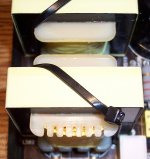
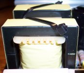
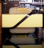
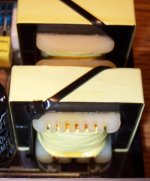
Here are some shots of them, maybe you can see something I am missing. I have seen on other 500's where the yellow tape heated much worse than these look and be ok. I never suspected them. These do not seem to change in temperature even as the little bit of square wave is sent to them. I actually suspected the caps, but they measured fine when removed.
Here are some shots of them, maybe you can see something I am missing. I have seen on other 500's where the yellow tape heated much worse than these look and be ok. I never suspected them. These do not seem to change in temperature even as the little bit of square wave is sent to them. I actually suspected the caps, but they measured fine when removed.
Attachments
OK. Lets' try something else first.
Remove one pair of outputs. Connect a jumper between the positive and negative speaker terminals. With all remaining transistors clamped, power it up. If it remains powered up without drawing excessive current, confirm that you have rail to rail oscillation on the remaining pair of outputs. Post what you find.
Remove one pair of outputs. Connect a jumper between the positive and negative speaker terminals. With all remaining transistors clamped, power it up. If it remains powered up without drawing excessive current, confirm that you have rail to rail oscillation on the remaining pair of outputs. Post what you find.
Would I be able to apply logic to choosing which pair of outputs?
I can't remember at this point if all four were blown or if just a pair, but if I choose the side that was driven by the resistors that burned, would that be logical? Or am I making too much of it and it won't matter?
I can't remember at this point if all four were blown or if just a pair, but if I choose the side that was driven by the resistors that burned, would that be logical? Or am I making too much of it and it won't matter?
After rewiewing post #15, I did briefly have the ~39VDC between both the +/- and GND, so wouldn't that mean the output inductors are probably OK?
Not being able to measure all of the possible points at the same time, earlier I was monitoring both the Voltage and Amperage panel meters on the power supply as well as the points I needed to measure with the DMM. The voltage does not sag much at the PS. With the 3 Ohm resistor inline, I measured between B+ and GND at the amp and it sags to <9V which should shut this amp down.
Would this indicate there are still problems in the main power supply?
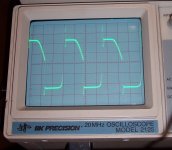
Here is the set up to develop this waveform.
Removed rectifier.
DMM in line to measure current.
5A fuse in line to B+.
No resistor in line to B+.
Scope set to 5V Div. 5uS Div. Probe x10.
It takes ~15 seconds for the square wave to develop on the left rectifier pad while the current draw climbs to 1.96A and stays there. The right rectifier pad is the same, just inverse (the rounded corner is on bottom).
It seems to me that is a little too much current draw to idle without rectifier installed and I should see a bit better square wave. True?
Even so, it appears that the majority of the problem exists after the rectifier.
Attachments
- Status
- This old topic is closed. If you want to reopen this topic, contact a moderator using the "Report Post" button.
- Home
- General Interest
- Car Audio
- JL Audio 500/1 v1 Rev. 10 Boards #2