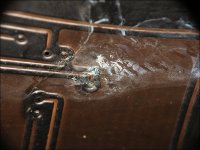
Was the board absolutely clean? Sometimes the corrosion simply looks like a light haze on the board.
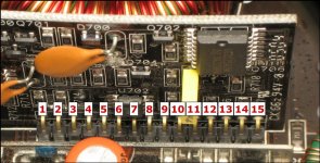
Post the DC voltage for the terminals on the power supply driver board. Refer to the photo for the numbering of the pins. Place the black meter probe on the amplifier's ground terminal. Place the red meter probe on the point where you need to measure the voltage.
PS Driver board
Pin 1:
Pin 2:
Pin 3:
Pin 4:
Pin 5:
Pin 6:
Pin 7:
Pin 8:
Pin 9:
Pin 10:
Pin 11:
Pin 12:
Pin 13:
Pin 14:
Pin 15:
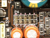
Also post the voltage on the 10 pin connector on the preamp board.
Preamp board
Pin 1:
Pin 2:
Pin 3:
Pin 4:
Pin 5:
Pin 6:
Pin 7:
Pin 8:
Pin 9:
Pin 10:
Post the DC voltage for the terminals on the power supply driver board. Refer to the photo for the numbering of the pins. Place the black meter probe on the amplifier's ground terminal. Place the red meter probe on the point where you need to measure the voltage.
PS Driver board
Pin 1:
Pin 2:
Pin 3:
Pin 4:
Pin 5:
Pin 6:
Pin 7:
Pin 8:
Pin 9:
Pin 10:
Pin 11:
Pin 12:
Pin 13:
Pin 14:
Pin 15:
Also post the voltage on the 10 pin connector on the preamp board.
Preamp board
Pin 1:
Pin 2:
Pin 3:
Pin 4:
Pin 5:
Pin 6:
Pin 7:
Pin 8:
Pin 9:
Pin 10:
Attachments
- Status
- This old topic is closed. If you want to reopen this topic, contact a moderator using the "Report Post" button.
- Home
- General Interest
- Car Audio
- jl audio 100/1