In many designs, this roll off is compensated for by peaking in the electrical response by resonance between the transformer leakage inductance and the panel capacitance. The amount of peaking is controlled by a damping resistor which is usually put in series with the transformer primary where it can do double duty and provide transformer core saturation protection as well. [/url]
It seems here your describing the effect of LC oscillations, I would have to agree that adding a resisitor is the same as acting a damper to tame the resonant freq of an LC oscillator, if I recall it correctly I think fres=1/LC.
Do you think having this control with using a resistor this way, would be better to use a potentiometer.
Regardless of the reason, lower mass is better from your standpoint as well as mine. Since it is easier to get something to accelerate if it has a smaller mass.
You seem to have a more holistic understanding of all the principles involved. Today I plan on doing some lump circuit analysis of the electrical portion. I know of Arend-Jan, he has a great jig for the mylar, and at one point gave me a paper that Streng wrote dealing with charge movements in a circulat paper.
Thanks for the references.
I've been down with a cold for a few days now and maybe it's the fever talking?
Is there a reason why you can't stretch the Mylar film on a flat bed and then "roll" the back stator onto it?
You could still stretch it only lengthwise.
If the stator already holds the curved shape all should be fine?
Then just cut the mylar, apply the coating and "roll" on the front stator?
I'm assuming foam tape for mounting.
I think a press jig, like a vice would work better, in assuring that you apply it uniform. I would try to mount both panels at the same time this way, with the mylar streched and coated sandwiched between them. Also, I think just vertical spacers (3m tape) is all you need, my panels are 12" wide, so I will have two vertical spacers (tape) ever 4 inches. Including the edges (with overhang) this gives 4 vertical supports. Im not worried all that much about stray capacitance. or the reduce output. If you are instead of using vertical stripes, use double sided foam disks instead. This will set the spacing, make more of the mylar move, more output, and reduce stray cap.
Is there a reason why you can't stretch the Mylar film on a flat bed and then "roll" the back stator onto it?
Also, when you say, roll, are you referring to what a metal worker would do to curve the metal. Or are you just referring to how you would simply place them on the mylar bed.
Feel better.
Yeah right, you will consume the double amount of coating.
Don't do it.
Do you know if the original Quads were coated double sided, could you clarify?
Thanks
Do you know if the original Quads were coated double sided, could you clarify?
Thanks
Yes the original Quad ESL has both sides of the diaphragm coated. I know this for a fact.
Yes the original Quad ESL has both sides of the diaphragm coated. I know this for a fact.
Were the woofers diaphragms coated on both sides as well?
Or was it just the mid-tweeter diaphragms that were coated on both sides.
It seems here your describing the effect of LC oscillations, I would have to agree that adding a resisitor is the same as acting a damper to tame the resonant freq of an LC oscillator, if I recall it correctly I think fres=1/LC.
Yes, the effect is from the series resonance of L(transformer leakage inductance) & C(panel capacitance). Your memory was pretty close
") , formula to calculate resonance is:
, formula to calculate resonance is:Fres = 1/(2*PI*sqrt(LC))
Since the panel output is proportional to the voltage across the panel the resulting output is a 2nd order LP(low pass) response. Depending on the amount of damping resistance the response can be under-damped, critically-damped, or over-damped. Here is a link to some measurements I took of the voltage reaching an ESL panel. Attachment 3 shows the effect of the damping resistance value on the response.
http://www.diyaudio.com/forums/planars-exotics/161485-step-up-transformer-design-20.html#post2147513
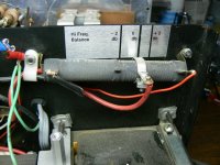
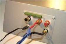
You could use a potentiometer. I believe Acoustat used them in their ealier designs. The problem you will run in to is the resistor needs to be fairly high wattage, I'd say 10W - 20W. Also, since these resistors are fairly low in value (1 - 5 ohm typical) the wipers contact resistance can change enough over time to require readjustment. Later Acoustat interface units used adustable power resistors like that shown in Attachment 1. A German ESL manufacturer, Capaciti, who posts on this forum from time to time provides binding posts on the back of the interface box of their Element 160 where you can attach the damping resistor of your choice. See Attachment 2. I believe Sound Lab still uses potentiometers in their ESL interfaces to adjust the high frequency response. See Attachment 3.Do you think having this control with using a resistor this way, would be better to use a potentiometer.
Attachments
Also, when you say, roll, are you referring to what a metal worker would do to curve the metal. Or are you just referring to how you would simply place them on the mylar bed.
Feel better.
In this instance I was referring to the mounting technique.
The stators will however have to be roled before hand to get the actual curved shape.
Is there a way to avoid pre-rolling the stators?
Is there a way to avoid pre-rolling the stators?
If you´re satisfied with a smaller bend, you can do as I explained earlier.
Is there a way to avoid pre-rolling the stators?
Well, if you use something maleable like aluminum then maybe. But youll have a hrad time with soldering to it. Also, Aluminum is light weight and the tension on the mylar, well youll have too have a properly engineered frame.
Steel is what I went with, and the amount of effort you would have to exert to build a press jig, that not only presses (mattes) and shapes the metal is going to be very time consuming and probably expensive. Also it just seems to be a lot of things have to go right all at the moment the stators are taped to the film, for this to be worth trying. But if you did you could mass produce those babies!
Just go to a metal shop and they can roll the steel for you to whatever radius of curvature you need.
Later Acoustat interface units used adustable power resistors like that shown in Attachment 1. A German ESL manufacturer, Capaciti, who posts on this forum from time to time provides binding posts on the back of the interface box of their Element 160 where you can attach the damping resistor of your choice. See Attachment 2. I believe Sound Lab still uses potentiometers in their ESL interfaces to adjust the high frequency response. See Attachment 3.
thanks for those shots!, Love the first one, is that washer looking thing on the pot the wiper?
Why not just use an equalizer to compensate? They must be worried more about how these issues would cause the speaker to fail electrical and mechanically. Because any rolling off can be compensated with an EQ.
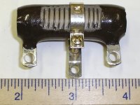
The washer is an adjustable center tape that is clamped in position. Attached is a close up pic of a similar adjustable power resistor.thanks for those shots!, Love the first one, is that washer looking thing on the pot the wiper?
Why not just use an equalizer to compensate? They must be worried more about how these issues would cause the speaker to fail electrical and mechanically. Because any rolling off can be compensated with an EQ.
Remember Acoustat was in the business of selling ESLs to the public. It makes sense to me if they could provide high frequency compensation adjustment with one resistor to do it rather than requiring potential buyers to buy another piece of electronics to put in their signal chain.
For DIY purposes feel free to use an EQ to compensate for the roll off if you desire, especially if you will already be using one to flatten the falling low frequency response due to dipole roll off and possibly for crossover as well. However, it is still good practice to put at least 1 ohm of resistance in series with the primary of your step-up transformers to protect the amplifier from trying to drive a short if the transformer core saturates.
Attachments
On the problem of soldering alu, before painting the stator, just mount a small brass rivet at edge of the stator as a solderable connector point.
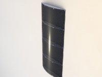
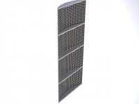
If you want alu/steel stators with identical curvature, which is necessary for for good stereo sound image, you can do this:
Produce, with a band saw, 5-6mm thick aluminum "bridges" with the preferred curvature/shape and screw them on the back of the back stator. Place the bridges at the same height as every other foam support. The skrew skulls are hidden by the foam supports. This also adds weight to the Els, a good thing.
The front stator doesn't need to be bent, just let it get its shape when the els package is mounted in a frame. ( this is true only for max .8 mm steel, 1,5 mm alu)
Attachments
Remember Acoustat was in the business of selling ESLs to the public..
True, but some day we should see an ESL that has nothing in it, no crossover, no step up (head amp), maybe just a bias supply. We all know how finkiky some audiophiles can be so let them decide what they want to do. If they want active xovers the company could put them it. If they want passive xovers well then they have that perferred option as well. I agree with less electronics in the signal chain is desirable. But we do need to get the job done. IMO I think having the xovering done before amplifcation helps a great deal in keeping distortion down.
In my design, the panels are only for mids and highs, the lows will be a traditional transmission line, folded horn design. I think dipole cancellation happens more at low freqs, something around the wavelength that is comparable to 1/4 the largest characteristic length of the esl panel. So since I am handling the lows this way I should be ok. You could try and use the dipole radiation field to your advantage, but you will most likely just get more destructive interferance then constructive interference. Some people just put very expensive baffled sound panels behind the speaker panels on the wall, to trap the dipole field from reflecting any more forward.
I can afford to build these speakers, as I bough these materials a year ago. But I cant afford to power them. Does anyone have an afforable way to power esl hybrids?
My dream is to have passive xovers, and have 3 mono blocks for each of the lows, mids, and highs. 6 mono block+passive xovers+2 head amps (bias supply)+equalizer=what 40-50k!!!
I really need someone to help me with advise of buying just a two channel amp that can power at least just the panels. And then another two channel amp to power the lows. Anyone with aforable ideas. afforable for me is like spending 1-2K for the two channels.
Something that is know to work wonders with capactive loads.
Anyone shelve out the dough for those plitron esl stepups? I cant see how they would be worth spending $700 for two of them. When I can spend what like $100-200 for something equivelent.
Thanks Bryan
BOLSERST in post 28 of yours image one, the acustats pot, how hard is it to get to, to adjust it? Do you repair as hobby/passion, or professional? I enjoy fixing vintage audio stuff. Thanks again for taking the time to post those shots. Be well.
The Acoustat damping resistor is easy to adjust as it is at the top of the interface box.
Simply loosen the screw holding the moveable clamp, slide it left of right depending if you want to boost or cut the top couple octaves, then tighten the screw.
Repairing audio and antique radios(pre-1930 especially) is a hobby.
ESL building has been an on and off interest for 15 years or so.
If you want alu/steel stators with identical curvature, which is necessary for for good stereo sound image, you can do this:
Produce, with a band saw, 5-6mm thick aluminum "bridges" with the preferred curvature/shape and screw them on the back of the back stator. Place the bridges at the same height as every other foam support. The skrew skulls are hidden by the foam supports. This also adds weight to the Els, a good thing.
The front stator doesn't need to be bent, just let it get its shape when the els package is mounted in a frame. ( this is true only for max .8 mm steel, 1,5 mm alu)
The only curved panels I ever built I used this concept. I built a frame with curved cross braces made from MDF. Stators were 1.5mm aluminum. The rear stator was attached to the MDF frame with 3M foam tape, the whole stator taking on the curved shape of the cross braces.
QUOTE]
Jonas in your photos are those screws left there, or is that just part of your pressing jig. Did you turn them on? If you leave them, then Id been worrying more then id have to about discharge then id have too.
As you have under your posts, stop thinking and just do it already. Certainlt applies to me.
Bryan
- Status
- This old topic is closed. If you want to reopen this topic, contact a moderator using the "Report Post" button.
- Home
- Loudspeakers
- Planars & Exotics
- Jig and stretch for curved ESL?