These are small permanent M3 countersunk screws, bridges and screws were mounted before powder coating.
After powder coating, strips of insulation tape were placed over the screw heads and then the horizontal membrane support foam strips were placed on the tape. The tape and foam were made 4 mm wider than the screw heads to prevent arcing...
I later discovered that the tape could be omitted, when I started to use clear see trough "foam" from MMM which itself worked as an insulator between screw heads and film.
Attachments
Looks interesting, I wonder if 1mm steel stators would work?
On the problem of soldering alu, before painting the stator, just mount a small brass rivet at edge of the stator as a solderable connector point.
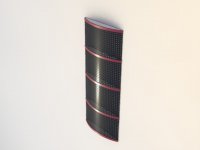
If you want alu/steel stators with identical curvature, which is necessary for for good stereo sound image, you can do this:
Produce, with a band saw, 5-6mm thick aluminum "bridges" with the preferred curvature/shape and screw them on the back of the back stator. Place the bridges at the same height as every other foam support. The skrew skulls are hidden by the foam supports. This also adds weight to the Els, a good thing.
The front stator doesn't need to be bent, just let it get its shape when the els package is mounted in a frame. ( this is true only for max .8 mm steel, 1,5 mm alu)
Looks interesting, I wonder if 1mm steel stators would work?
No problem, I use .8 mm mainly because when powder coating, the hole edges tends to get more coverage, hence less arcing.
I also have a warning! Once you have started experimenting with these things and associated hardware, it´s very likely that you´ll never stop!
I've been building electrostats for thirty years, starting at 15, and I don't believe there are anything on this planet that is as interesting as these animals!
Last edited:
No problem, I use .8 mm mainly because when powder coating, the hole edges tends to get more coverage, hence less arcing.
Thats nice, can you do the powder coating yourself, or did you outsource? expensive? ill look into it.
and jonus i have a warning once you start modeling these speakers electrical,mechanical, and acoustical, youll never stop. Worse then that, i seem to have only solutions for on axis, so in the end to get a meaningful result, youd either have to make a whole lot of assumptions, and hope your results still predict the reality of what will be. Or, you can put the results that I cant do into a computer simulation. hit enter and wait a long time. my coding abilities are less then elegant these days, and running the simulation to find the radiation pattern in the near zone took so long that my computer just gave up and frooze. Thanks B
The panels are taken to a local powder coater, not expensive,
around 10 dollars per panel. The hard thing is to persuade the operator to make two layers of coating. For some reason, they are not so happy to do this.
Well I just looked into this (wikipedia).
Powder coating - Wikipedia, the free encyclopedia
And it sort of reminds me of anodizing, but having the end product insulate for our purpose and to color. Being the process is electrostatics
.
Do you recall what type was used in your design? Thermoplastic or thermosets? I think it might be a thermosetting kind?? But in terms of edge coverage will one be better?
Dont think abrasive preprep is good, like sandblasting? rather a chemical cleaner is probably ideal? I remember reading where one esler would first spray using automotive spray paint gun, a mist first layer, allow a short ten minute tact time, then a second layer. I think the reasoning for the first coat to be just a thin mist was to improve the adhearsion of the spray in subsequent coatings. This seems better then sandblasting that would probably just create more edges.
Sorry If this sounds like im just hashing this out. But I never built an esl, wanted to for some time, started, got stuck, delays, money issues, etc...
the fludized bed method of application reminds me of wave soldering, when large circuit boards would be soldered in one shot by having some kind of heated solder bath, with a wave (vibrating) through it. I was thinking of doing this earlier just to round out the edges of the perforations. This powder coating seems ideal for this app.
Anything I should specfically require before i do this next week? From what I read on the above wiki link (sounds a little like wiki leaks
") bawling ) this seems ideal, fast, and cheap? Unless I run these things to a pizza place to use their ovens, ill have yet one more thing be outsourced.
bawling ) this seems ideal, fast, and cheap? Unless I run these things to a pizza place to use their ovens, ill have yet one more thing be outsourced. This is great, love this forum, Thanks everyone!
Bryan
I usually powder coat first and then two layers of urethane paint with hardener.
I think the ordinary thermoplastic method is used. One important thing is to keep record
and mark the panels so that you know which side of the panels is smooth, and let this side face the membrane.
(When the metal sheet is hole punched, the side where the punch comes out has rough
hole edges)
Before I drag my panels to the powder people, I sand down the worst edges with a machine sander. It's cleaned before painting by the powder people.
I sand down the worst edges with a machine sander. It's cleaned before painting by the powder people.
ok, thanks, when i got the stators cut and rolled last year, i did what I could with a dremil tool to round out all the sharp edges, looks ok, and seems to look pretty good compared to those 'eslers' that have had great success.
Lastly, I'm sure there is already a thread for this and ill look around here. But, any afforable way to power these?
I have some kind of professional grade yamaha two channel amp that my uncle graped before his employer was going to throw it out.
I dont think it will do the job, its only 150W mono, or 75W stereo. Yamaha P2075.
I also have a vintage marantz, which I just restored. This wouldnt be able to power them but wanted to use this marantz purely for the phono input for my TT.
Thanks
Bryan
I usually powder coat first and then two layers of urethane paint with hardener.
I think the ordinary thermoplastic method is used. One important thing is to keep record
and mark the panels so that you know which side of the panels is smooth, and let this side face the membrane.
(When the metal sheet is hole punched, the side where the punch comes out has rough
hole edges)
Before I drag my panels to the powder people, I sand down the worst edges with a machine sander. It's cleaned before painting by the powder people.
Found local powder coater, will do it for $110 and can flash test them.
Jonus, when you used the magnetic strips did you ever have a problem holding the films tension? Using the double side tape, the friction provides the shear force to keep the tension. With the magnetic strips you only have a normal force. Any ideas on the type of magnets to consider, the ones I was thinking of using are from McMaster-Carr have max pull of 4-24 lbs/ft
McMaster-Carr
Also, do you think its possible to mount the bike tube jig into the esl frame. So If we need to tension the film down the road, after much playtime we could just pump more air into the tube? What source dis you use for your magnetic strips if they worked well for you.
Thanks Again,
Bryan
If you refer to these speakers: Picasa Web Albums - Jonas - Drop Box
the magnetic tape is just for clamping the stators together, the film tension is provided by the stainless, inside rubber lined steel frame.
The film tension on those speakers can also be adjusted by the tension adjuster you can see on the back side. You can use any brand of mag tape, preferably 1 to 2 mm thick.
If you refer to these speakers: Picasa Web Albums - Jonas - Drop Box
the magnetic tape is just for clamping the stators together, the film tension is provided by the stainless, inside rubber lined steel frame.
The film tension on those speakers can also be adjusted by the tension adjuster you can see on the back side. You can use any brand of mag tape, preferably 1 to 2 mm thick.
Thanks Jonas, Charlie mention that you have the frame holding the tension. I started this project about a year ago and I really should just reroll the stators flat for many reasons. What I was going to do if I were to just use 3m double side for the spacers was to tension the mylar flat, then press the every slight curved stators with the tape on to the tensioned mylar. However, with magnets I will have to go back to the drawing board or reroll them flat to do something similiar as you have done.
Thanks Bryan
and the stators I have are steel so with that weight I'd be hard pressed.
The package tape you use to prevent wrinkles and HF reflections of the steel frame? Unless you have edge fields, if the magnets clamp tightly on to the film the mylar outside the magnets should not vibrate nor should any vibrations inside the area enclosed by the magnets propagate past the magnet boundary?
Its a good idea to use that tape as some kind of stress release. Great Job with these speakers, your ahead of many designers. You have built into the design that you will eventually have to maitain these esl. This is very wise.
Just to be clear, you have attached the HV bias supply directly to the steel frame, and via contact will charge the mylar? If so why not just use copper ring around insulated frame that accepts the HV bias supply contact?
How do they sound today? How long have they been on for?
Great Job,
Bryan
Near field measurements shows that sound wave travel past the magnetic stripes, but not to any high degree. The packing tape is mainly for strengthening the film to cope for the weight of the stators.
This is a very minimalistic design, so using the stainless frame for two purposes is perfect!
Besides, I don't like using copper strips because of their tendency to corrode.
Also, its very fun to see peoples reaction when they touch the speaker.
The charge is perfectly safe, fed trough ten 10 Mega ohms resistors.
I get a much bigger electric shock when I touch the power button on my amp after sitting in our very static inducing sofa!
Maybe due to the vacuum sputtered film, they still play very good, I can hear no difference as to when they were new. They have playing
now for almost six years, time flies!!!
Last edited:
Near field measurements shows that sound wave travel past the magnetic stripes, but not to any high degree. The packing tape is mainly for strengthening the film to cope for the weight of the stators.
This is a very minimalistic design, so using the stainless frame for two purposes is perfect!
Besides, I don't like using copper strips because of their tendency to corrode.
Also, its very fun to see peoples reaction when they touch the speaker.
The charge is perfectly safe, fed trough ten 10 Mega ohms resistors.
I get a much bigger electric shock when I touch the power button on my amp after sitting in our very static inducing sofa!
Maybe due to the vacuum sputtered film, they still play very good, I can hear no difference as to when they were new. They have playing
now for almost six years, time flies!!!
Thats Great. I was thinking about your design all day today. When you look at the speakers it looks like there floating.
A minimalistic design is the best, less parts, less likely youd see complications. Ockham's Razor.
Stronger magnets would pinch the mylar better preventing soundwaves from moving past them over to the statorless area. I think you charged the whole membrane including the statorless area? Could you sputter coat the membrane where you have the coating applied in such a way that you deliver the charge via a small line to the larger (driven) area on the membrane (the area behind the stators) then any electric field lines from the edges of the stators want matter any, since all the free charge is only where we want to drive the membrane.
To be able to sputter a pattern like that you would just have to have a ground (zero potential) that has the same pattern (like a rectangle meets a narrow line).
Having the mylar oversized, as you do, has a lot of advantages. One it helps prevent breakdown between the front and back stators. Second, It allows you to design a way to retension the membrane without having to design an overly complicated frame to house and mount everything. It allows you to use the magnets, well your the designer you know all the advantages. My hat is off to you.
In your previous builds of using copper for the charge ring did you have postive or negative bias on the membrane?
Can I ask what you do for a living? Did you outsource the sputtered coating?
Thanks for the thoughts
Bryan
Bryan,
I began in 1984 to work as an engineer at Kodak, here in Malmo, Sweden.
In 2007, I decided that enough is enough, and started developing loudspeakers as a full time job.
The whole film is conductive. Due to some lucky circumstances, I got hold of 300 meters of this very expensive sputtered film. Its probably the same film that the well known electrostatic loudspeaker manufacturer in Delaware uses.
As you mention, its very hard to drive this speaker to arcing, although the stator coating isn't that super good. Maybe this is due to the hanging stator design?
Bryan,
I began in 1984 to work as an engineer at Kodak, here in Malmo, Sweden.
In 2007, I decided that enough is enough, and started developing loudspeakers as a full time job.
The whole film is conductive. Due to some lucky circumstances, I got hold of 300 meters of this very expensive sputtered film. Its probably the same film that the well known electrostatic loudspeaker manufacturer in Delaware uses.
As you mention, its very hard to drive this speaker to arcing, although the stator coating isn't that super good. Maybe this is due to the hanging stator design?
that is some luck. lets see... 300 meters, been building esl since 1984, so highly unlickly youd have any of that sputtered film around, right.
Wonder what they coat it with? I had a couple qoutes from local powder coaters, one told me they could coat with many desirable coatings, but only to 1-2 mils thick. Another coater could do the same but had the right gun so not to lose the ground potential when adding more coats. I wonder how thick your stator coats are.
If you look at the electric field of a simple parallel plate cap, and study the fields around the edges of the plate, they will, from the outside of the plate go from one to the other. This is bad edge field effect to have, since around edges the e-field is very large .e-field will always be perpendicular to conductor, and with a sharp conductor you will have many e-field lines in a small area and by defination this increases the electric field strength. If it gets large enough to break the air down you will arc.
In your case it makes it very difficult for the e-field to do that. Im not sure if you suspended because you had to with the magnets not being strong enough to hold the tension, or not to cram the frame with the re-tensioning jig and the esl mount. It certainly works well on many levels.
kodak, dont even get me started. recently, found old kodaflex in gradmas basement, cleaned and rived it. In perfect working order to find out that it accepts 620 film. Kodak made the camera of course to sell the film, with no interchangeable lenses, come on. No worries, since in their laziness they just respooled 120 film on propriatary 620 sized spool.
I dont want to derail the topic. But, I would like to send you an email when im done with this design, or later on when i can send photos of the built esls. I have read many ideas on esls for quite some time and have been building for two years, using the magnets is by far one of the most innovative and progressive improvements ive seen. Mainly, I repair vinage audio. I Appreciate your feedback. Enjoy your esls.
- Status
- This old topic is closed. If you want to reopen this topic, contact a moderator using the "Report Post" button.
- Home
- Loudspeakers
- Planars & Exotics
- Jig and stretch for curved ESL?