
AndrewT,
It is very nice to see that your stability results are the same as mine - no compensation is necessary. I ended up leaving a 33pf miller cap in place as it slightly improved the overshoot. Any progress on your runaway offset yet? I am still perplexed by it as I had no such problem. Have you tried output source resistors yet?
It is very nice to see that your stability results are the same as mine - no compensation is necessary. I ended up leaving a 33pf miller cap in place as it slightly improved the overshoot. Any progress on your runaway offset yet? I am still perplexed by it as I had no such problem. Have you tried output source resistors yet?
Yeah, I was also wondering about that cos I didn't notice anything strange behaviour in the offset. I've been running mine at between 0.5 & 0.75 amps and it seems to behave normally.
Andrew, did you notice this anomaly in both of your amps ? If not I wonder if it could be a poor connection in your trimmer.
The other thing that I'm puzzled about is Hugh's concern about turn on thump. As far as I'm aware anyone who has built it does not think this is an issue - my experience is similar to Gregs i.e. can hardly hear it above the noise of inserting the mains plug but perhaps it's because my CL gain is so low ( 11 ).
My boards are due in about 4 days and also my possessions should arrive soon so I will be able to do some A/B comparisons and look at some square waves.
I inserted 4 x 0.1 ohm resistors in all four power lines in each amp and this brought some more refinement so I think you will enjoy that when you try it Greg. My values are 1000uF / 0.1R / 10,000uF - levels of ripple seem acceptable. I will be trying all singing all dancing choke regulation also just to see if that is significantly better.
My next mods will be trying a few different VAS devices and then after that I will leave these amps as a reference and build new ones to check out DC offset reduction measures.
mike
Last edited:
Mike,
I personally don't give too much credence to switch on thumps as long as the speaker cone doesn't leave the basket.....
BUT, I'm conscious that many audiophiles are terrified of them and think it jeopardises their expensive speakers, so I surmise that this is an important marketing and acceptance issue.
If you say there's no thump, I'm beside myself with joy, thanks for raising the issue.....
Cheers,
Hugh
Isn't it nice to see we have a great amplifier emerging that requires no compensation, servo or thump protection, and only 4-5 active devices...
Mikelm I will be very interested to see how you go with the dc coupled version.
I do intend to ultimately use a CRC power supply for my final version so it's good to hear that it made a worthwhile improvement. I will start experimenting again on Monday when I return to work.
Mikelm I will be very interested to see how you go with the dc coupled version.
I do intend to ultimately use a CRC power supply for my final version so it's good to hear that it made a worthwhile improvement. I will start experimenting again on Monday when I return to work.
Last edited:
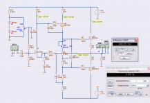
I did setup a Headphone Amp in spice.
I used IRF610/9610 TO-220 output and same transistors for VAS.
Driven by a VBE-multiplier based on IRF610.
Bias was 100mA Class A.
There is no need for big LATERALS for a headphone amp.
The good thing is that people has got 2SK170 and IRF610/9610 at home.
(Of course one could build a normal Fetzilla
and use a Headphone output jack.)
Attachments
Last edited:
I meant to provide a link:
http://www.diyaudio.com/forums/head...phone-amp-jlh-output-stage-9.html#post2610655
- keantoken
http://www.diyaudio.com/forums/head...phone-amp-jlh-output-stage-9.html#post2610655
- keantoken
Mikelm,
What filter are you currently using on the rails between the vas and output?
All,
Something I should have mentioned earlier but forgot to is that I am using the GR version of the 2SK170, not the BL version. Unfortunately I only have a model for the BL version which is why it is on my schematics.
My apologies if this has caused any inconvenience.
What filter are you currently using on the rails between the vas and output?
20 ohms + 470uF
Mikelm, Stan,
Please try placing a good quality 22uf electro across your bias spreader. You won't be disappointed. I think you will be very, very pleasantly surprised as I was 5 minutes ago.
Stan, this will fix your treble issue, I promise.
Thanks to Hugh and JLH for the inspiration.
Edit: someone please tell me why this works!?
The 22uf cap (I use 47uf 6.8V bipolar caps, (NX black gate would be awesome, but uobtainable)) stabilizes the bias spread...and keeps the upper and lower devices tracking better...If the input was configured as a differential pair, one could use a cap there as well with the same treble calming effect...
Current (and best so far) schematic
Thanks Miib.
All,
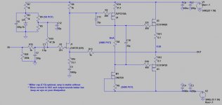
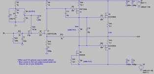
Here is my current schematic. Same as last time except for the 22uF bias spreader cap. The amp sounds truly exceptional in its current state. The bias spreader cap has really cleaned up the treble and removed a slight hint of harshness that was there before. Sound is also a bit more fluid and relaxed.
If you can deal with the heat and decreased life, more current in the vas and output is better but the values I have posted are a good compromise.
On the agenda for this week is the construction of what I believe will be the best and penultmate version (as per Hugh's PCBs), with supply rail filters for the low power stages and a special new hybrid bootstrap/ccs VAS. Also, a new device for the VAS which is ideally suited to 20mA current but has far nicer parasitic properties than the IRF9610.
Thanks Miib.
All,
Here is my current schematic. Same as last time except for the 22uF bias spreader cap. The amp sounds truly exceptional in its current state. The bias spreader cap has really cleaned up the treble and removed a slight hint of harshness that was there before. Sound is also a bit more fluid and relaxed.
If you can deal with the heat and decreased life, more current in the vas and output is better but the values I have posted are a good compromise.
On the agenda for this week is the construction of what I believe will be the best and penultmate version (as per Hugh's PCBs), with supply rail filters for the low power stages and a special new hybrid bootstrap/ccs VAS. Also, a new device for the VAS which is ideally suited to 20mA current but has far nicer parasitic properties than the IRF9610.
Attachments
Mikelm, Stan,
Please try placing a good quality 22uf electro across your bias spreader. You won't be disappointed. I think you will be very, very pleasantly surprised as I was 5 minutes ago.
Stan, this will fix your treble issue, I promise.
Thanks to Hugh and JLH for the inspiration.
Edit: someone please tell me why this works!?
Hi Greg,
I replaced the bias spreader (1uF film cap) with a 22uF 50V bipolar electro cap - Hitano brand from my parts bin, I think it is better than the polar electro. I also increased the gate-stopper of my ZVP2110 from 200ohm to 330ohm, the treble is smoother.
The input capacitance of N-type (600pF) Renesas L-MOSFET is much lower than the P-type (900pF). I am currently using a 180ohm gatestopper for N & 200ohm for P. I may change it to 270ohm for N & 180ohm for P.
Cheers, Stanley
Hi, Stanley
You are right - if you are aiming for the same rolloff at output mosfets (gates) you must use a bigger gate resistor for N-ch because of its lower Cgs. 270R for N-ch and 180R for P-ch seems fine. You may try also 240R for N-ch and 150R for P-ch (even with a small theoretical imbalance).
regards,
Tibi
Stanley, I endorse Tibi's comment. I had thought 470R and 330R, but I suspect 270/150 is better. It is not always realised that the gate stopper can be used to tailor the subjective bass response of the amplifier - the difference is astonishing.
Thanks for bringing this up, it's important!
Greg, the 22uF bias spreader cap works by firmly holding the control voltage at the point of turn on and turn off of the output devices. The larger capacitor means that the bias voltage is completely unaffected by charge migration into and out of the mosfet gates, and it's value is so large and the time constant so slow it tends to remove the oscillatory transition during switching. Result is more defined drain current, better control - and more HF resolution.
Cheers,
Hugh
Last edited:
- Status
- This old topic is closed. If you want to reopen this topic, contact a moderator using the "Report Post" button.
- Home
- Amplifiers
- Solid State
- JFET input, MOSFET VAS, LATERAL output = Perfect!!