Danspy,
Where you been!? Are you still listening to this amplifier? What are your current feeings about the sound? Is the circuit you just posted the one you are currently listening to?
Btw, 4700uf seems small for an output cap....
I can't Rush when i build Amplifiers, too much tension blinds my hearing.

At the moment I hear this circuit.

The wan I just posted was only a to Fet modified drawing of the Black Devil Amplifier.
VAS MOSFET
Hi Lineup,
I tried to build the official Fetzilla power amp using a old PCB. I don't have the IRF9610 so I used IRF4905 and IRF4905 does not work too well. I got about +21V at the output. I swapped the BC546 & BD139 & IRF4905 and it made no difference.
I removed the output L-FETs (K1058/J162) and converted it to a Fetzilla pre-amp & it gave similar result.
Here is some voltage readings:
Vsupply = 24.1V
Gate of k170 = 0.1mV
Drain of k170 = 19.8V (I-ips=4.3mA)
Source of k170 = 0.14V
I used a trimmer (213R) to substitute R15 & R16.
For U5, I used BC546C
Collector of BC546 = 0.14V
Emitter of BC546 = -22.65V
Base of BC546 = -22.05V
Base of BD139 = -22.05V
Collector of BD139 = 20.8V
Emitter of BD139 = -23.21V
Source of IRF4905 = 23.35V (I-vas=16mA)
Gate of IRF4905 = 19.8V
Drain of IRF4905 = 20.8V
I just ordered a few IRF9610 from RS and hopefully that they will arrive in a week or so. I will try Swordfishy/Hugh's version as well. I think that the magic of this design lies with the type of MOSFET for the VAS.
Cheers, Stanley
It is easy to use Fetzilla as preamplifier.
Just remove the output stage and take output from VAS.
One can adjust for more or less current.
In my diagram it is 11mA. This is standard for VAS.
A good project to begin with
Distortion is low and sound should be good.
But this remains to see/hear when somebody
builds Preamplifier Fetzilla.
.
Hi Lineup,
I tried to build the official Fetzilla power amp using a old PCB. I don't have the IRF9610 so I used IRF4905 and IRF4905 does not work too well. I got about +21V at the output. I swapped the BC546 & BD139 & IRF4905 and it made no difference.
I removed the output L-FETs (K1058/J162) and converted it to a Fetzilla pre-amp & it gave similar result.
Here is some voltage readings:
Vsupply = 24.1V
Gate of k170 = 0.1mV
Drain of k170 = 19.8V (I-ips=4.3mA)
Source of k170 = 0.14V
I used a trimmer (213R) to substitute R15 & R16.
For U5, I used BC546C
Collector of BC546 = 0.14V
Emitter of BC546 = -22.65V
Base of BC546 = -22.05V
Base of BD139 = -22.05V
Collector of BD139 = 20.8V
Emitter of BD139 = -23.21V
Source of IRF4905 = 23.35V (I-vas=16mA)
Gate of IRF4905 = 19.8V
Drain of IRF4905 = 20.8V
I just ordered a few IRF9610 from RS and hopefully that they will arrive in a week or so. I will try Swordfishy/Hugh's version as well. I think that the magic of this design lies with the type of MOSFET for the VAS.
Cheers, Stanley
Attachments
But does it really matter if total THD is say less than 100ppm ?
Me has two preamps which are half same and half different.
Both are 2 box affairs in the >20k$ range, heavy artillery power supplies, both fully balanced designs, both monotonically decreasing harmonic pattern.
One is all-FET, minimal parts, open loop, high bias currents, not exactly amazing thd figure.
Other is FET/BJT, high parts count CCS Hell, NFB design, extreme low distortion.
One is spicey, other mellow, both sound very very pleasant.
Sort of like Indonesian sambal.
Use 1/2 a tablespoon of sugar and 1/2 a tablespoon of salt, or 1 tbsp of sugar and 1 tbsp of salt, one is mellow and the other is spicey, but both are pleasant.
Use other than 1:1 sugar and salt, sambal fckd up, regardless how much sugar and salt.

(idiot sauvage thinks it sorta like saying FET better than BJT, and vice versa)
Jacco,
if I understand correctly (please do rectify me if I am wrong) while half a tablespoon of salt makes them half different and half a tablespoon of sugar half the same that is by no means better than vice versa yet pleasant in any case - kinda stuck situation due to $ range equilibrium.
if I understand correctly (please do rectify me if I am wrong) while half a tablespoon of salt makes them half different and half a tablespoon of sugar half the same that is by no means better than vice versa yet pleasant in any case - kinda stuck situation due to $ range equilibrium.
Stanley,
Can you post your schemat with voltages highlighted?
There will be a good reason, but we are a bit in the dark with the schematic.....
Hugh
Hi Hugh,
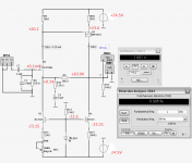
I have attached the schmatics, the voltages are in RED.
It is possible that I made some mistake with the wiring, I will replace the Q1 with a PNP BJT tonight.
Cheers, Stanley
Attachments
Stanley,
Because your fb resistor is a high 10K, necessary to reduce loading on the VAS (IRF9610), any current not passed by the lower left CCS (U5) will pass through this resistor. In fact, only 2mA through the 10K resistor (50% of the drain current through the jfet), will generate the +20V offset you are seeing.
Solution: The CCS is drawing too much current. For the jfet biasing shown, it should draw around 4.1mA. This corresponds to 330R between emitter and negative rail of the CCS, so simply replace the 100R trimpot with a 200R trimpot, OR, increase R15 to 270R and use the existing 100R trimmer.
Cheers,
Hugh
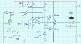
This is a revised version of my 1st servo idea after some spice research
The low end -3dB point is now at about 0.3Hz - nicely subsonic.
I will initially build without this servo connected and do a careful comparison before finally adopting it.
I have another idea which would use a light dependant resistor - ala lightspeed attenuator - which may be more "invisible" and luckily it will be quite easy to swap between the different versions.
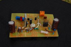
I'm currently working on a board layout using blank veroboard & pins so I can conveniently try different amplifier & servo versions.
I bet SWF can't believe I'm going so slow !
cheers
mike
The low end -3dB point is now at about 0.3Hz - nicely subsonic.
I will initially build without this servo connected and do a careful comparison before finally adopting it.
I have another idea which would use a light dependant resistor - ala lightspeed attenuator - which may be more "invisible" and luckily it will be quite easy to swap between the different versions.
I'm currently working on a board layout using blank veroboard & pins so I can conveniently try different amplifier & servo versions.
I bet SWF can't believe I'm going so slow !
cheers
mike
Attachments
jcx,
Agreed.ruling out bjt a priori for any position in a amplifier circuit is simply pretentious posturing - not engineering
Agreed. BJT should be the obvious choice there and for numerous other positions.bjt can be excellent for current transfer as in cascoding the fet gain stages - and in fact are superior to jfets in the same circuit position due to the high gm/low impedance they present to the drain of the cascoded fet
Mike....
There also exists some photo Jfet based variable resistors...that could be interesting for the servo
http://www.fairchildsemi.com/ds/H1/H11F1M.pdf
There also exists some photo Jfet based variable resistors...that could be interesting for the servo
http://www.fairchildsemi.com/ds/H1/H11F1M.pdf
FFT Analysis
Hi All,
Today my new 100meg scope arrived. It's only a cheapie, but here is the FFT analysis at 1kHz, 8V p-p into 7.2R for the bootstrap VAS version.
Y axis is 10dB per division, x axis is 1.5kHz per division.
The noise floor is similar to my sig gen alone...
Interested to know if this is a decent result, or if I'm even using it properly. There's a few different types of FFT to choose from and I'm not sure this is the right one.
Look forward to your comments.
Attachments
Mikelm, looks good. I really like the idea of using an LDR for the servo. Please keep me posted.
Do yourself a favour and build the ccs vas version first. It's the best for multiple genres. Bootstrap is nice for vocals and that's about it.
Take your time, I'm eagerly awaiting your impressions. I hope it lives up to your expectations.
By the way, did you get an small signal fets to try at the input?
I'm waiting on some irfp9240s. Gonna try it with vertical fets biased at 2A!
SWF,
Your FFT looks good to me
That's my plan
Someone lent me 4 x 2sk170s and I have some slightly higher spec LSK170s coming in the post.
Cool, I mean HOT ! I mean awesome . . .
I await your subjective assessment
Your FFT looks good to me
Do yourself a favour and build the ccs vas version first. It's the best for multiple genres. Bootstrap is nice for vocals and that's about it.
That's my plan
By the way, did you get an small signal fets to try at the input?
Someone lent me 4 x 2sk170s and I have some slightly higher spec LSK170s coming in the post.
I'm waiting on some irfp9240s. Gonna try it with vertical fets biased at 2A!
Cool, I mean HOT ! I mean awesome . . .
I await your subjective assessment
There also exists some photo Jfet based variable resistors...that could be interesting for the servo[/url]
Thx for this, I'll check them out.
Have we heard any subjective comparison between these variable Jfets & regular LDR's ?
I have used LDR's for volume control and if correctly implemented they sound very good indeed.
Tip on the IRF240/9240: Don't run over 38W dissipation; they really don't appreciate going over 40W unless you have forced air cooling.....
John, VAS needs to be low gate capacitance (no more than 200pF), fast fast fast, up to 2W free air dissipation, Vgs threshold around 3.8V, and typically 200mS of gm at around 20mA. In fact, SWF's choice of 20mA has more to do with extracting gm from the IRF9610 than any drive issues of the output devices. gm drops precipitously at very low drain currents......
Hugh
- Status
- This old topic is closed. If you want to reopen this topic, contact a moderator using the "Report Post" button.
- Home
- Amplifiers
- Solid State
- JFET input, MOSFET VAS, LATERAL output = Perfect!!