Would stick to the Jfet....and add a Hawksford cascode...
Hugh you re already compromising the jfet by increasing the rails and lowering the current. My experience with SK170 is that it sounds better with more current and best with currents close to idss. The cascode helps to maintain the distortion profile when you push it with larger signals
the 9510.. has lower input capacitance and may be worth a try also...
Last edited:
All Fet please...
Dear chaps ( and maybe even chappettes?),
please do try and stick to all Fet? - It was the original design intention's from Line-Up and it is where 'the gold seam' is IYDHO...
The advantage of a MosFet for input is as proven, that it draws absolutely no current from the input and therefore eases the DC issues in this particular single front end configuration.
However - there might be a very good reason to stick with the 2SK170 (or maybe something similar Fet wise) for sound reasons?
Toshiba and others has more available Fet's in the Voltage range required, so please don't despair!
There will be a good Fet part available here with the desired properties within reason...
I have to second Hugh and pay homage to Greg for an amazing job being done here!")
Please keep it up all?
All the very best
DocO, Svenzhen, PRC
Dear chaps ( and maybe even chappettes?),
please do try and stick to all Fet? - It was the original design intention's from Line-Up and it is where 'the gold seam' is IYDHO...
The advantage of a MosFet for input is as proven, that it draws absolutely no current from the input and therefore eases the DC issues in this particular single front end configuration.
However - there might be a very good reason to stick with the 2SK170 (or maybe something similar Fet wise) for sound reasons?
Toshiba and others has more available Fet's in the Voltage range required, so please don't despair!
There will be a good Fet part available here with the desired properties within reason...
I have to second Hugh and pay homage to Greg for an amazing job being done here!
Please keep it up all?
All the very best
DocO, Svenzhen, PRC
Hmm, narrowing it down, I would suggest we need a njfet with 100V rating, around 50mS yfs, and Idss of maybe 5mA.
That should be best.
However, that said, it is very difficult to hit the sonic target with distortion measurements, so if anyone has ideas about nfets to use, I'm all ears. Once we have a few to try, it's all hands on deck to get them by pigeon post to Greg for sonic testing.
And sonic testing is the go, here, not distortion measurements. It's already at extremely low levels, so with Greg's 31 year old ears, he da man.....
Cheers,
Hugh
ruling out bjt a priori for any position in a amplifier circuit is simply pretentious posturing - not engineering
bjt can be excellent for current transfer as in cascoding the fet gain stages - and in fact are superior to jfets in the same circuit position due to the high gm/low impedance they present to the drain of the cascoded fet
bjt can be excellent for current transfer as in cascoding the fet gain stages - and in fact are superior to jfets in the same circuit position due to the high gm/low impedance they present to the drain of the cascoded fet
I think this point is understood and has already been been discussed here with the advantages of BJTs in mind but there is the OP to to keep in mind, too. That's what has made the thread a little more interesting for me, at least.ruling out bjt a priori for any position in a amplifier circuit is simply pretentious posturing - not engineering....
By sneering openly at 'pretentious posturing', you alienate others and discourage their efforts. Fortunately, others here are more practical and sociable.
Having just done the parametric search, there is a dearth of higher voltage jfets with suitably low Idss, and so a cascode may be just the ticket. But your suggestion, however valid, could be put more sociably, more as participant, less as judge....
Hugh
Having just done the parametric search, there is a dearth of higher voltage jfets with suitably low Idss, and so a cascode may be just the ticket. But your suggestion, however valid, could be put more sociably, more as participant, less as judge....
Hugh
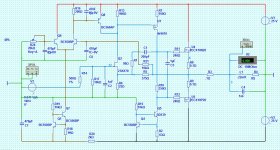
proposed servo idea 1
Here is my 1st shot at a servo circuit - shown in brown
It acts on i/p stage current.
It acts in parallel to a fixed resistor adding about 10% current to achieve "zeroing"
time constant of about 5 seconds.
neg rail filtered down to about -6 volts
We abandoned LTP in this amplifier circuit for the sake of speed but this cct is designed to move like a snail so LTP now gives the advantage of accuracy.
My goal is to make this servo sonically invisible. I really do not want to introduce any extra noise into the i/p stage.
I am not concerned about how many extra transistors this adds even though I do realise I could probably simplify the CCS somewhat without sonic penalty. My only concern is "does it perform it's action without affecting the sound".
any comments ?
Attachments
Mike,
We did not abandon the LTP for reasons of speed, more for reasons of distortion profile.
A properly balanced LTP cancels even order distortion, but does nothing to reduce odd order. The singleton is no better with odd order, but does not cancel even order.
However, your LTP does the servo heavy lifting elegantly!
Hugh
Last edited:
Well, I have not done any checks but "the man" said he stayed with a single i/p device when he updated his simple class A because it gave an advantage with phase / stability over a LTP - that's what I was referring to when I said "speed" - please excuse my sloppy parlance
So it looks like we have at least two advantages + the "making it simple" advantage which some of you must think I've just blown by adding a servo - hehe
So it looks like we have at least two advantages + the "making it simple" advantage which some of you must think I've just blown by adding a servo - hehe
No, Mike, you want to eliminate the caps, which is reasonable, and the servo is the only way to do it.....
The LTP has a major disadvantage sonically that I can find; it has an S shaped transfer curve which tends to compress high amplitude signals. This tends to play down the bass. A singleton has much more bass subjectively, although the FR curve does not show, why I have no idea.
Hugh
The LTP has a major disadvantage sonically that I can find; it has an S shaped transfer curve which tends to compress high amplitude signals. This tends to play down the bass. A singleton has much more bass subjectively, although the FR curve does not show, why I have no idea.
Hugh

Almost always, I have heard an increased resolution with lowering offset.
Thx for this feedback from your experience
Almost always, I have heard an increased resolution with lowering offset.
compare a -20dB signal, ref. maximum power, to the DC output offset.Thx for this feedback from your experience
Now compare a -60dB signal ref that average level of -20db, i.e. -80dB ref maximum power.
Maximum power is ~20Vpeak.
Average music level is ~2Vpk.
Quiet passage is ~2mVpk.
Output offset could be anywhere between 1mVdc to 1000mVdc.
Compare the offset voltage to the signal peak during a quiet passage.
Low level resolution could be a further 20dB to 30dB below this.
If the signal has an interfering level that is 100times larger, then could the audibility of the wanted signal be compromised?
If those numbers don't mean much then think of this analogy.
Pull a bow string using a spring balance. Use the force from the spring balance to pull the bow string to 100mm from straight.
Now apply a tiny force to create 1mm of resonant (100 times smaller than the offset) vibration to the pull point.
Compare this to applying the same 1mm of vibration force to the straight (non offset) bow string.
Do you think the resulting vibrations will be identical in both cases?
Last edited:
Hugh,
Yes, but they are less invasive in that position and if the feedback circuit has no cap, then the feedback can counter whatever colourations those caps add.
The i/p & o/p caps normally have have no such amelioration.
Danspy has added FB after the o/p cap but that feedback is insulated from the jfet source by yet another eletrolytic - for me it feels like a bad dream - hehe.
Anyway, all these theoretical details are of little consequence to me when this simple fact is, having tried it both ways, I have found that I just don't like the sound of caps in the signal path and, in the nicest possible way, nothing anyone can say will convince me otherwise - but I might try teflon one day
Btw, 4700uf seems small for an output cap....
Yeah - but the feedback will help to counter that
4700uF and 8ohm speaker have an F-3dB turnover frequency of ~4Hz.
Some listeners say that this does not affect the bass coming out of the speakers.
I would be hard pushed to audibly detect that extreme low bass roll-off, even though I adopt a 1.5Hz to 2Hz F-3dB frequency filter at my power amp inputs, because it sounds right.
Some listeners say that this does not affect the bass coming out of the speakers.
I would be hard pushed to audibly detect that extreme low bass roll-off, even though I adopt a 1.5Hz to 2Hz F-3dB frequency filter at my power amp inputs, because it sounds right.
Can this be powered with +/- 35V rails?
What are T1 - T4 ?
- Status
- This old topic is closed. If you want to reopen this topic, contact a moderator using the "Report Post" button.
- Home
- Amplifiers
- Solid State
- JFET input, MOSFET VAS, LATERAL output = Perfect!!