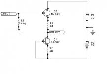
The real circuit had no input resistor. That was added by someone who drew up the schematic. It works fine with the J201 and the MPF102. The real thing used an E230 or 2SK30A.
I'm using this design. so omit R1 and wire the pickup straight to the gate? are the other components correct?
I'm using this design. so omit R1 and wire the pickup straight to the gate? are the other components correct?

R1 is only in there for RF suppression. I don't use it myself.
I increase C2 to 5µF for better low end response.
R1 is only in there for RF suppression. I don't use it myself.
I increase C2 to 5µF for better low end response.
just bought a bunch of NOS 2SK30A's for $2 to see what they sound like. The Vgsoff specs look better than the J201's.
R1 is only in there for RF suppression. I don't use it myself.
I increase C2 to 5µF for better low end response.
I built this improved design I found on the web using the 2SK30A-O. I had to lower the R4 source resistor to 2.2K to get the Vd to 4.7V. When R4 was 12K the Vd was only 1.8V. The 2SK30A is the best sounding JFET I've used so far. But the gain is way over the top, even with the gain knob all the way off. so it is clipping like the 2SK117. might be due to C1 boosting the signal too much.
these are the components I installed:
R1 22K
R2 (none)
R3 (none)
R4 2.2K
R5 100K
C1 100uF electrolytic
C2 10uF electrolytic
C3 10uF electrolytic
Q1 2SK30A-O (Vd - 4.7)
D1 1N4001
P1 100K linear
I think if I remove C1 it will stop the over-the-top signal gain
I built this improved design I found on the web using the 2SK30A-O. I had to lower the R4 source resistor to 2.2K to get the Vd to 4.7V. When R4 was 12K the Vd was only 1.8V. The 2SK30A is the best sounding JFET I've used so far. But the gain is way over the top, even with the gain knob all the way off. so it is clipping like the 2SK117. might be due to C1 boosting the signal too much.
I build them with MPF102s. At the minimum the gain is unity.
It's supposed to be a self biasing circuit.
I get no clipping at all, even with the gain cranked up. I never use it that way because it's so loud.
I build them with MPF102s. At the minimum the gain is unity.
It's supposed to be a self biasing circuit.
I get no clipping at all, even with the gain cranked up. I never use it that way because it's so loud.
I got the numbers mixed up. When the source resistor is 12K the Vd is 8 volts. I installed a trimpot as the source resistor and when it is at 2.2K the Vd is 4.7 volts and the signal was clipping. I turned the trimpot back up to 12K and it stopped the clipping. I thought in order to get the full frequency response and dynamic range of the JFET the Vd should be half the power supply. I noticed when the Vd is at 8V it doesnt have the same brilliance as 4.7V. I'll have to experiment with removing the C2 cap and adjusting the source trimpot
thats looks like an outboard design. I'm making this preamp to put in the bass
Like I said, I use this INSIDE my basses, which means it's onboard. Then again, I am using two 9v batteries, and I am not sure this circuit will perform well on just 9volts.
Like I said, I use this INSIDE my basses, which means it's onboard. Then again, I am using two 9v batteries, and I am not sure this circuit will perform well on just 9volts.
do you have a diagram for it. I'd like to check it out.
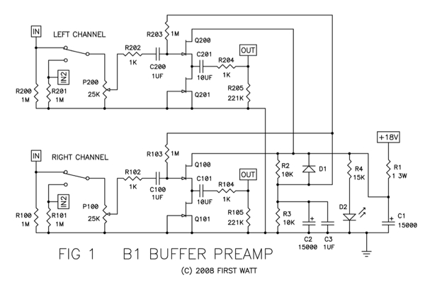
This is the thread where it is being discussed (llloooooooooooooonnnnnggggg).
B1 buffer discussion
And this is where the original article can be found:PassDIY B1
I removed the input switching and also didn't use a volume control in front.
B1 buffer discussion
And this is where the original article can be found:PassDIY B1
I removed the input switching and also didn't use a volume control in front.
This is the thread where it is being discussed (llloooooooooooooonnnnnggggg).
B1 buffer discussion
And this is where the original article can be found:PassDIY B1
I removed the input switching and also didn't use a volume control in front.
looks like an easy build. just have to find matching 2SK170's. some of the values need to be adjusted. I dont think R1 is needed if running on batteries. C1 and C2 can be lowered to 100uf. C101 can be a 10uF electrolytic to save space
I built this improved design I found on the web using the 2SK30A-O. I had to lower the R4 source resistor to 2.2K to get the Vd to 4.7V. When R4 was 12K the Vd was only 1.8V. The 2SK30A is the best sounding JFET I've used so far. But the gain is way over the top, even with the gain knob all the way off. so it is clipping like the 2SK117. might be due to C1 boosting the signal too much.

these are the components I installed:
R1 22K
R2 (none)
R3 (none)
R4 2.2K
R5 100K
C1 100uF electrolytic
C2 10uF electrolytic
C3 10uF electrolytic
Q1 2SK30A-O (Vd - 4.7)
D1 1N4001
P1 100K linear
I think if I remove C1 it will stop the over-the-top signal gain
Why did you omit R2 and R3 ?!
Why did you omit R2 and R3 ?!
R2 is there to eliminate switch pops and R3 is for blocking RF frequencies. It doesn't matter because I put them back in and it still clipped.
looks like an easy build. just have to find matching 2SK170's. some of the values need to be adjusted. I dont think R1 is needed if running on batteries. C1 and C2 can be lowered to 100uf. C101 can be a 10uF electrolytic to save space
Man, you are incorrigible! <grin!> Why don't you first try building it exactly how it was designed, and THEN try changing it, "if you must". Aw, never mind...
Anyway, you probably already know this, but, as far as C101 is concerned, since it needs to be a non-polarized cap, to replace it with electrolytics you should actually use TWO, of double the value, in series, back-to-back, with a high-value resistor in parallel with each one. So that would be two 22uF in series, with neg connected to neg, and something like a 1 Meg R in parallel with each of them. That would give you an 11 uF non-polar cap made from electrolytics. (You can try omitting the parallel resistors. Most people do.)
However, a film cap would probably sound SO much better, especially there! Metallized polypropylene is the way to go, for audio caps, if at all possible. But polyester would also sound WAY better than electrolytics. Film caps also last at least 20-50 times longer than electrolytics.
WIMA has some nice 4.7 uF 50V metallized polyester "box" caps that only have a 7.2 mm x 7.2 mm footprint, and are 13 mm high, with a 5 mm lead spacing, which list for $2.24 qty 1 in my July 2010 mouser.com catalog. You could parallel two of those in a 7.2mm x 14.4mm area. That's only a 0.28 x 0.57 inch footprint, i.e. just a little bigger than 1/4 x 1/2 inch! The WIMA part number of those is MKS2-4.7/50/10.
And Cornell Dubilier has their "small size" DME series, which includes a 10 uF 100V metallized polyester film cap that's only 1.02 inch long, 0.45 inch wide, and 0.827 inch tall, with lead spacing of 0.886 inch, listed for $4.43 qty 1 at mouser.com. DME1W10K-F.
Or, for $15-40+, you could get a nice fat 10uF metallized polypropylene.
Cheers,
Tom
Last edited:
If you use two 9volt batteries, no need for the complex bias network. If J-FETs are matched (buy a U440) no need for capacitors either(U might want one at the output for that good tummy feeling).
with no coupling caps 18 volts and going into the amp. that design is going to clip like crazy
hello.
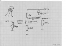
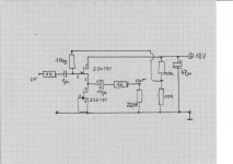
made a sim with the 2sk170bl in the afternoon.see attached schematic.
and built that with some spareparts i had laying around. my 2sk170 has an idss around 8,2ma..........so i measured nearby 6v drainpotential in my circuit (foto).and i have not built in the pot at the input because the function generator has one.
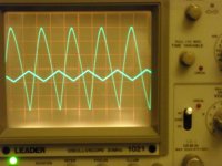
the o-scope foto shows beginning distortion at 6vpkpk output with 0,8vpkpk input signal (triangle).
sorry,made a typo in my last schematic(post 30): ofcourse the jfet is a 2sk117 (and not 2sj117).
greetings
made a sim with the 2sk170bl in the afternoon.see attached schematic.
and built that with some spareparts i had laying around. my 2sk170 has an idss around 8,2ma..........so i measured nearby 6v drainpotential in my circuit (foto).and i have not built in the pot at the input because the function generator has one.
the o-scope foto shows beginning distortion at 6vpkpk output with 0,8vpkpk input signal (triangle).
sorry,made a typo in my last schematic(post 30): ofcourse the jfet is a 2sk117 (and not 2sj117).
greetings
Attachments
Last edited:
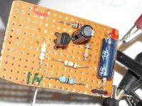
hello paul.
so here is a minimalistic schematic of the buffer amp. i left out the big elcos because it should fit into the body of your guitar.
psu is two 9v batteries in series..........
the foto shows the circuit on perfboard,i used spareparts which i had on hand.
greetings
so here is a minimalistic schematic of the buffer amp. i left out the big elcos because it should fit into the body of your guitar.
psu is two 9v batteries in series..........
the foto shows the circuit on perfboard,i used spareparts which i had on hand.
greetings
Attachments
thanks. I just got the matching FET's in the mail. I'll put it together and hope it doesn't clip
hello paul.
so here is a minimalistic schematic of the buffer amp. i left out the big elcos because it should fit into the body of your guitar.
psu is two 9v batteries in series..........
the foto shows the circuit on perfboard,i used spareparts which i had on hand.
greetings
- Status
- This old topic is closed. If you want to reopen this topic, contact a moderator using the "Report Post" button.
- Home
- Live Sound
- Instruments and Amps
- JFET bass preamp clipping problem