a peak hold circuit based on an opamp will drive the DMM to give you a better feel for maximum signals from the guitar.
Your 18V supply limits maximum sinewave output just before clipping into a very high impedance load of about 6Vac.
It is normal for the maximum audio signal to be 10 to 20dB below that theoretical voltage to get good performance from the amplifier.
That limits your maximum output to between 600mVac and 2000mVac.
What is the gain of the circuit? Divide the maximum output by the gain to find the maximum input to the circuit. Now compare that max input to the peak hold value the DMM gives you. Peak hold gives the peak of a varying signal, convert the mVac to an equivalent Vpk by applying sqrt(2) factor.
Last edited:
a peak hold circuit based on an opamp will drive the DMM to give you a better feel for maximum signals from the guitar.
Your 18V supply limits maximum sinewave output just before clipping into a very high impedance load of about 6Vac.
It is normal for the maximum audio signal to be 10 to 20dB below that theoretical voltage to get good performance from the amplifier.
That limits your maximum output to between 600mVac and 2000mVac.
What is the gain of the circuit? Divide the maximum output by the gain to find the maximum input to the circuit. Now compare that max input to the peak hold value the DMM gives you. Peak hold gives the peak of a varying signal, convert the mVac to an equivalent Vpk by applying sqrt(2) factor.
I got rid of one of the batteries and went back to 9V. I think 18V was contributing to the clipping problem. now the clipping is totally gone. now I can concentrate on fine tuning the tone coming from the preamp. This class A one transistor design has a very unique sound I never heard before from a bass. I'm still a beginner and have to learn all the electronic terminology and procedures. without the help from this forum I would have been totally lost. thanks again

hello.
made some simulations.......
r5 is gone (=zero).
rd=6,8k rs=130 psu=18V:
with 200mVpp the output is around 4Vpp,this gives a voltage gain around 20 times........rather big.
with 9V psu:
rd=22k rs=1,5k gain drops to around 7,5 times
and with rd=6,8k rs=390 gain is around 10 times.
perhaps you can use r5=1k or bigger against rf (gate stopper res against radio frequencies) if you don't need the input attenuator.
greetings
Last edited:
removing the 18V supply and substituting a 9V supply to make it not clip sounds like the amplifier was not biased properly for the 18v supply voltage.I got rid of one of the batteries and went back to 9V. I think 18V was contributing to the clipping problem. now the clipping is totally gone.
The chance that it might be biased properly for the 9V supply is low.
What is the bias current in the amp and what is the DC output voltage before the DC blocking capacitor?
hello.
made some simulations.......
r5 is gone (=zero).
rd=6,8k rs=130 psu=18V:
with 200mVpp the output is around 4Vpp,this gives a voltage gain around 20 times........rather big.
with 9V psu:
rd=22k rs=1,5k gain drops to around 7,5 times
and with rd=6,8k rs=390 gain is around 10 times.
perhaps you can use r5=1k or bigger against rf (gate stopper res against radio frequencies) if you don't need the input attenuator.
greetings
that seems to be the trick. getting the right attenuation from the pickups and getting the right ratio of the drain and source resistors before it is clips. when it is at 68k:390 at 9 volts (Vd 4.5V) the gain is too much and it clips and is noisy. right now it's 22.1K:1.5k at 9 volts (Vd 4.7V) and it doesn't clip and is noise-free. I'm going to lower the 22.1K and 1.5K gradually to see the point before it starts clipping. I tried 1K, 33K, and 68K at R5 and I got that over-the-top gain clipping distortion again.
Quote . right now it's 22.1K:1.5k at 9 volts (Vd 4.7V) and it doesn't clip and is noise-free. I'm going to lower the 22.1K and 1.5K gradually to see the point before it starts clipping. I tried 1K, 33K, and 68K at R5 and I got that over-the-top gain clipping distortion again.QUOTE
........22k:1,5k looks good in the sim (gives a Vd nearby 5V,but Id is low 0,2mA).i think it needs the input voltage divider,perhaps you try it with the trim pot (fine tuning).
greets
........22k:1,5k looks good in the sim (gives a Vd nearby 5V,but Id is low 0,2mA).i think it needs the input voltage divider,perhaps you try it with the trim pot (fine tuning).
greets
Quote . right now it's 22.1K:1.5k at 9 volts (Vd 4.7V) and it doesn't clip and is noise-free. I'm going to lower the 22.1K and 1.5K gradually to see the point before it starts clipping. I tried 1K, 33K, and 68K at R5 and I got that over-the-top gain clipping distortion again.QUOTE
........22k:1,5k looks good in the sim (gives a Vd nearby 5V,but Id is low 0,2mA).i think it needs the input voltage divider,perhaps you try it with the trim pot (fine tuning).
greets
when I tried the voltage divider all the pickup switches popped real loud. I had an electrolytic cap with the positive facing the preamp and the switches still popped.
With the bass at its highest output (both pickups together in series) the DMM reads at 12.3K DC resistance and the voltage peaks at 15mV when I played the bass hard. I put 1M (2 x 2.2M) in front of R1 and left R1 at 500K. since both resistors are in parallel the sum is 350K going into the gate. I got rid of one the batteries, I think the extra voltage was contributing to the high gain clipping. I made the drain to ground 4.5V by adjusting the source resistor. It made a difference. Now I only hear slightly audible soft clipping when both pickups are together in series. When I play hard I don't get that horrible distortion anymore. Looks like I'm almost there
oops the sum is 1M going into the gate
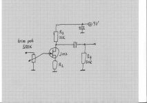
schematic (sketch) ref. post 27.
added the 1M trimpot and added 10uF electrolytic in front of that with the positive facing preamp. found out the clipping threshold is 680K to the gate. anything below 680K is clip city. the best tone so far. when it was 1M to the gate it sounded like the mids were being scooped. gonna play the bass for awhile and see if it clips during any of the pickup selections. This bass has 7 switches with a total of 72 pickup options. I'm at these values now:
Q1 2SK117 @ 4.7 Vd
C0 10uF
R0 680K (1M trimpot)
R1 500K
R2 680 OHM (5K trimpot)
R3 10K
R4 100K pot
C1 47uf
C2 47uf
QUOTE ....... and added 10uF electrolytic in front of that with the positive facing preamp.
i would use a film/foil cap,perhaps 0,47uF or more.........make it big.
........found out the clipping threshold is 680K to the gate. anything below 680K is clip city. the best tone so far. when it was 1M to the gate it sounded like the mids were being scooped.
yes,that effect can come with the cable capacitance of your guitar cable i guess. your pickup has probably a few henry inductance (5H or so often seen) and your 4m..........5m long cable a capacitance around 500pF........and both create an overshoot in the midband,may say 3khz..... 5khz (with an imput impedance of 1meg or so).that was the reason why i used 500k because that reduces it a little bit.but this changes the sound too and you have to decide for yourself what's the best tone..............so i think your can play around with the input divider (500k or 1meg).........without changing your guitar cable (lenght).hope it works.
late now,good night.
Last edited:
had to go back to the J201. the 2SK117 can't take high output bass pickups without distorting. I had to sacrifice too much gain and tone to stop it from clipping. the J201 still sounds great but not as clear as the 2SK117. gonna build another boost using the MPF102 to see if it can handle the pickups
I have never been able to get a combination of acceptable sound and dynamic range on a 5 string with a single JFET amp. Been all over that. Lately I've been playing around with seriously low impedance pickups and a single OPA134. So far so good.
I put the 2SK117 preamp in the fretless PJ bass and was surprised at the results. nice clean boost. the mids and highs really shine through. since the pickups are are only 3.8K impedence is probably why it doesn't clip. the pickups on the 2 humbucker bass were 11.5K each, way too much for the 2SK117 to tolerate
Don't use that Tilman circuit. Do a search for the Alembic Stratoblaster. It's similar but doesn't clip and has variable gain.
Just change the output cap to 10µF.
I use these on basses all the time, and get no clipping.
If you still get clipping with the pickups in series, insert a series resistor with the input when the pickups are in series.
Just change the output cap to 10µF.
I use these on basses all the time, and get no clipping.
If you still get clipping with the pickups in series, insert a series resistor with the input when the pickups are in series.
Don't use that Tilman circuit. Do a search for the Alembic Stratoblaster. It's similar but doesn't clip and has variable gain.
Just change the output cap to 10µF.
I use these on basses all the time, and get no clipping.
If you still get clipping with the pickups in series, insert a series resistor with the input when the pickups are in series.
that was my next project to build. Since the input resistor is only 68K there is no way I can use the 2SK117. gonna try it with the J201
I use Nelson's B1 buffer on my basses and that works fine as well, with over 2v p-p coming out of passive pickups, you don't need that much gain anyway.
I've tried the Tillman, and in my trials J201 distorted way earlier than both 2SK170 and MPF102 (and I think I tried 2n5457 as well).
I've tried the Tillman, and in my trials J201 distorted way earlier than both 2SK170 and MPF102 (and I think I tried 2n5457 as well).
I use Nelson's B1 buffer on my basses and that works fine as well, with over 2v p-p coming out of passive pickups, you don't need that much gain anyway.
I've tried the Tillman, and in my trials J201 distorted way earlier than both 2SK170 and MPF102 (and I think I tried 2n5457 as well).
thats looks like an outboard design. I'm making this preamp to put in the bass
that was my next project to build. Since the input resistor is only 68K there is no way I can use the 2SK117. gonna try it with the J201
The real circuit had no input resistor. That was added by someone who drew up the schematic. It works fine with the J201 and the MPF102. The real thing used an E230 or 2SK30A.
Last edited:
- Status
- This old topic is closed. If you want to reopen this topic, contact a moderator using the "Report Post" button.
- Home
- Live Sound
- Instruments and Amps
- JFET bass preamp clipping problem