Thanks for the analysis AndrewT.
The noise does not bother me, it's the PC sound card floor noise, and the slop in 900Hz is the sweep generator problem.
i tray today to replace the capacitor, maybe it's the problem for the 120,150Hz slop.
Next time I post the reference plot.
Thank
The noise does not bother me, it's the PC sound card floor noise, and the slop in 900Hz is the sweep generator problem.
i tray today to replace the capacitor, maybe it's the problem for the 120,150Hz slop.
Next time I post the reference plot.
Thank
after read this, i think maybe cut the design to 2 pole.
even more, first watt B5 use 12 dB/oct too.
"
Q19 - Why do you use a 12 dB/oct crossover between woofer and midrange when the crossover to the tweeter is at 24 dB/oct ?
A19 - The crossover to the tweeter is at a steep slope to prevent lower frequency signals from pushing the dome into large excursions. For constant SPL the dome excursion increases at 12 dB/oct as you go down in frequency. Thus, a 12 dB/oct crossover would merely keep the tweeter's low frequency excursions constant, not reduce them. Since program material usually has larger low frequency than high frequency amplitudes, this could lead to inter-modulation distortion in the driver. In my work on crossovers (Ref. 17) I observed that the phase distortion, i.e. the all-pass behavior, of the 24 dB/oct crossover has no audible side effects in this frequency range. See Design Models F.
I also noticed then that the very low frequency part of the spectrum is audibly affected by the system's phase response (further observations in: L. R. Fincham, "The subjective importance of uniform group delay at low frequencies", JAES, Vol. 33, No. 6, p. 436, 1985). This is the reason for keeping the dc blocking high-pass filter in the woofer channel to a low 2 Hz cut-off, even though it provides less protection for over-excursion of the drivers.
At a 100 Hz crossover frequency the reduced phase distortion of the 12 dB/oct crossover gives more realism to the bass. The two 8" drivers, which roll off on their own around 40 Hz in the open baffle, can handle the extra excursion demands.
"
Hi,
thought my hints would make the issue obvious
In no4 of #248 the 2R are connected to gnd.
They are part of the filter and as such their value defines the filter function.
In no2 of #248 and #257 You sketched the 2Rs connected to the Bias network, which here adds 10k and 9k1 in parallel to the 2R value.
Seems You somehow guessed something like that, as You didn't use a 330k resistor for that branch.
No wonder the filter behaves not as expected but a lower crossover.
As You need a bias at the gate of the upper JFET connect bias to the 100R gate resistor (add another 330k between bias and the gate resistor)
jauu
Calvin
Well I found the first few pages of this interesting - that was until all the anti op amp hyperbole kicked in....
I have never built a discrete active filter, but I've built several op amp based ones, using the dreaded TI devices...
Its so amusing....
Once someone said to me "you'll never get a op amp filter to sound good"...
More snake oil.
I have been absolutely amazed by the difference in comparison to passive speaker level filters.
I don't doubt a discrete version can improve further upon the op amp filter - but its not going to be night and day...diminishing returns blah blah.
I always worry when I hear things like "huge open loop gain, sacrificed by unity feedback sucks the life out of music"
Utter tripe.
Hi,
thought my hints would make the issue obvious
In no4 of #248 the 2R are connected to gnd.
They are part of the filter and as such their value defines the filter function.
In no2 of #248 and #257 You sketched the 2Rs connected to the Bias network, which here adds 10k and 9k1 in parallel to the 2R value.
Seems You somehow guessed something like that, as You didn't use a 330k resistor for that branch.
No wonder the filter behaves not as expected but a lower crossover.
As You need a bias at the gate of the upper JFET connect bias to the 100R gate resistor (add another 330k between bias and the gate resistor)
jauu
Calvin
hi
yasss, its work, so simple !!
But only when i connected the bias to GND, why?
About the bias: connected it straight to the gate trough 330K(or 1M like B1) ? And the R to GND?
(i dont use the bias cap, only 2* 10K)
i want to build this filter according to the B1 buffer, so i give up for the stopper resistor, see nelson pass scheme in #248.
results: See the results and the scheme, now its 12db/oct
")
What about the curve change in 400-500 Hz? What is it? because there is no bias?
Thanks all
Attachments
Last edited:
Some progress
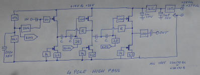
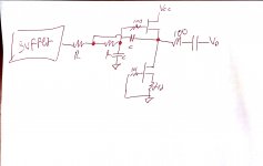
i build the HPF Exactly like AndrewT (pic-1), only 2 pole.
The results are best, the 220uf cap is important, the bias need to connected to R and its work, thanks.
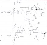
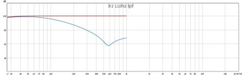
About the LPF i need HELP (pic-2)
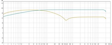
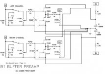
Build same scheme like pic-4, only 2 pole. but i have bump (550Hz) in the results(pic-2), try to replace the transistor, caps, resistor, nothing helps.
Whets wrong?
Thanks
i build the HPF Exactly like AndrewT (pic-1), only 2 pole.
The results are best, the 220uf cap is important, the bias need to connected to R and its work, thanks.
About the LPF i need HELP (pic-2)
Build same scheme like pic-4, only 2 pole. but i have bump (550Hz) in the results(pic-2), try to replace the transistor, caps, resistor, nothing helps.
Whets wrong?
Thanks
Attachments
Last edited:
Hi
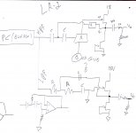
today i try another option. filter base on dual supply B1 buffer (see picture). the results is same.
the HPF is work great, the LPF is the same (CY connected to -VCC), bump in 550Hz. picture in #273
mybe its the 2sk246 (3-4ma IDSS) or Ciss=10pf ?
today i try another option. filter base on dual supply B1 buffer (see picture). the results is same.
the HPF is work great, the LPF is the same (CY connected to -VCC)
, bump in 550Hz. picture in #273mybe its the 2sk246 (3-4ma IDSS) or Ciss=10pf ?
Attachments
Last edited:

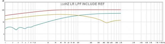
20-40Hz its ~95db (sorry for the Resolution)
1Khz its ~65db
my problem its not the 10db more or less, its the Understanding.
more important, this Phenomenon that the filter stop to fall is normal ???? if it is, i try to change the design until get the results.
Add another plot
thanks
1Khz its ~65db
my problem its not the 10db more or less, its the Understanding.
more important, this Phenomenon that the filter stop to fall is normal ???? if it is, i try to change the design until get the results.
Add another plot
thanks
Attachments
Last edited:
here is a modified B1 style LR4 showing the alternative output connection to avoid the lack of HF cut of the standard unity gain filter.
I'm not sure your result is showing the same problem, or a different error.
I see I downloaded this in February, i.e. after I built my low pass bass only filter.
There is at least one Thread that discusses this.
I'm not sure your result is showing the same problem, or a different error.
I see I downloaded this in February, i.e. after I built my low pass bass only filter.
There is at least one Thread that discusses this.
Attachments
- Status
- This old topic is closed. If you want to reopen this topic, contact a moderator using the "Report Post" button.
- Home
- Source & Line
- Analog Line Level
- JFET Active Crossover