Hi Marc,mpmarino said:I got this one over a year ago and it works great. Tips same size as the Hakko. The thing is great.
Still desperately seeking a couple boards")
desperately
I didn't see your previous post. I have 4 boards and can send 2 to you. Given the workload that I am having, I doubt that I will see any kind of soldering issue any time soon
 Let see I can dig out your email address -)
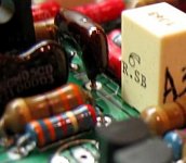
O.T. on soldering irons
I agree with Bob!
I may wear out the $3 tip for for my back-up Rat Shack 40W iron this week as much as I've been soldering on these PCB's; However, my $8 Weller WTC tip has lasted well over a year with regular use, plus you get constant temp control(i.e. not too hot/not too cold-just right)!
I got my Weller while in college and it lasted 20+ years (OK-I'm spoiled). Too bad they cost a fortune now(even on ebay).
-Chas
BP: We may be able to salvage your boards yet!
Please see the photo on how I start each resistor lead (solder top first, flip board and solder bottom(after trimming lead to 0.25-0.5"). Oh, and for a tightly-clustered bunch of components, I stuff and solder one at a time starting near the center of the group. Time consuming? yes. Problems? no.
Lesson learned:If buying surplus resistors, check lead material(avoid steel )! Cheaper isn't better!
I used throw away irons until I bought my... temperature controlled station. Results are worth it and the tips last a >10X longer than the cheap irons.
I agree with Bob!
I may wear out the $3 tip for for my back-up Rat Shack 40W iron this week as much as I've been soldering on these PCB's; However, my $8 Weller WTC tip has lasted well over a year with regular use, plus you get constant temp control(i.e. not too hot/not too cold-just right)!
I got my Weller while in college and it lasted 20+ years (OK-I'm spoiled).
Too bad they cost a fortune now(even on ebay). -Chas
BP: We may be able to salvage your boards yet!
Please see the photo on how I start each resistor lead (solder top first, flip board and solder bottom(after trimming lead to 0.25-0.5"). Oh, and for a tightly-clustered bunch of components, I stuff and solder one at a time starting near the center of the group. Time consuming? yes. Problems? no.
Lesson learned:If buying surplus resistors, check lead material(avoid steel )! Cheaper isn't better!
Attachments
Bob,
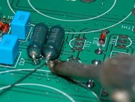
This is what I believe was the the problem. I used a resistor with extreemely thin coating over steel leads. I buffed the leads and Chas did not. He was able to get his to adhere to the solder because he had not buffed the lead. I, instead, tryed to make the lead even smaller removing all the tinned coating. I then tried to solder the the steel wire to no avail. Does this make any sense??
BP
tryonziess said:Doesn't anyone use a cheap 8.00 dollar 40 watt iron anymore. I never did enough soldering to justify spending 80.00 dollars for a decent station. When the little guy dies I just buy a new one.
Tad
Heck, I run a 260/200W Weller gun on the big stuff! These things are 'acquired' over the years.
Re: Re: Boards....
Set up a DC supply with a limiting resistor (30V and 1k2 will do)
This passes ~8mA through a 20V Zener. A 400mW Zener will not run too warm @ 170mW.
Now measure all your Zeners.
find pairs that add up to a fixed voltage near 40V, eg 19.9+19.2=19.7+19.4=19.1+20 etc.
Job done.
Final check on the assembled and powered PCB. See if the total Zener voltages are within 0.1V
matching the near 40V required from the pair of series Zeners is easy.rob3262 said:Matching zeners was as bad as small signal transistors. I'm beginning to think that 5% is useless! My reference voltages range between 19.2 and 19.8V Maybe I'm anal but I was hoping to exact match 6 boards!
Set up a DC supply with a limiting resistor (30V and 1k2 will do)
This passes ~8mA through a 20V Zener. A 400mW Zener will not run too warm @ 170mW.
Now measure all your Zeners.
find pairs that add up to a fixed voltage near 40V, eg 19.9+19.2=19.7+19.4=19.1+20 etc.
Job done.
Final check on the assembled and powered PCB. See if the total Zener voltages are within 0.1V
I actually had set the supply for a 2ma flow thru 1k resistor, DC voltage was ~ 21.5v during the test.
I really hope I didn't fudge the test as all the diodes are paired off already. And four soldered to a board. Matching the first 16 was easy, but as the pool got smaller, well....
The last set of zeners have a .1v mismatch. I was satisfied to get that result.
I really hope I didn't fudge the test as all the diodes are paired off already. And four soldered to a board. Matching the first 16 was easy, but as the pool got smaller, well....
The last set of zeners have a .1v mismatch. I was satisfied to get that result.
that 1.5V across the resistor will affect the accuracy of the testing.
if you put a 19.9V Zener in it will leave 21.5-19.9=1.6V across the 1k0, passing 1.6mA through the Zener, ~32mW (<10% 0f 400mW rating).
now put in a 20.1V Zener. It will pass just 1.4mA. this is even less than the 32mW of the previous and will result in a voltage measurement that is not comparable to the first test.
You need a more consistent current source. Either a higher regulated voltage or a CCS.
I recommend that Zeners dissipate >=10% of rated power for consistent voltage regulation.
But the final test is in the powered amp, that is the one that matters.
I thought most of the quality resistors we use today had PURE copper leads. Am I way out in left field on this? I always try to buy a major name brand item and hoped for good parts. They seem to bend like copper.
OK, I think I will buy a nice solder station -- any other good choices. If they last for several years the money is well spent. Mpmarino -- how long is the lead on that unit you posted as a suggestion. Sometimes the work area gets cluttered and I need quite a long lead to solder.
Andrew -- How critical is the zener match in this amp? What might you expect if they are off buy .5 - 1 volt.
The Zeners don't have to add up to exactly 40V.
But, I reckon the two sides should fairly closely match.
The Zener voltage affects the balance of current through the LTP.
You can measure the 4 halves of the 2 LTPs by the voltage drop on the Re. This should be as precise as you can get it, aim for a total spread of <=0.5%.
But, I reckon the two sides should fairly closely match.
The Zener voltage affects the balance of current through the LTP.
You can measure the 4 halves of the 2 LTPs by the voltage drop on the Re. This should be as precise as you can get it, aim for a total spread of <=0.5%.
Wanted: setup to match output transistors
Hey!
Anyone here located in Northern Cal. and have the setup to measure/match power transistors?
I would like to measure our group's pool of (same models) output devices so I can group together matched sets for each board.
I would be willing to travel and pay or trade some nice DIY audio stuff (such as transformers, heat sinks, caps, cables etc.) for the priviledge of using your setup.
Please email me.
TIA
-Chas
Chas,
I assembled a little test unit with a 30 volt wall wart, a couple of regulators, some spare caps and a DVM. Probable got 3.00 dollars tied up in the whole thing. I just change resistors for TO-220 devices. It seems to work pretty good. I got all of my output devices for my A-75 matched to .01 or better. It should work just as well with BJT outputs. It is not pretty by any standards. Lots of silicone and hot melt glue mounted to a piece of Lexan. I got some electrical harness connectors from a truck at work with the same lead spacing as the transistors. You just plug em' in and go.
Use a clothespin to hold them to a piece of copper for a hearsink. Some people place them in a box to eliminate drafts. You can do a bunch while watching a movie with the wife.
You need to make some noises every now and then so she knows you are listening. My wife does not like to be ignored. Our projects!!! After 30 years of marriage you learn a few things.
Tad
Nice trick to learntryonziess said:
You need to make some noises every now and then so she knows you are listening. My wife does not like to be ignored. Our projects!!! After 30 years of marriage you learn a few things.
Tad
I assembled a little test unit with a 30 volt wall wart, a couple of regulators, some spare caps and a DVM.
Tad,
Would you mind sending me a photo or wiring diagram of your measuring setup?
TIA
-Chas
tryonziess said:Mpmarino -- how long is the lead on that unit you posted as a suggestion. Sometimes the work area gets cluttered and I need quite a long lead to solder.
Excellent point-
I don't have it in front of me but now that you mention it, I recall the iron's cable being on the shorter side.
PS- Thanks Fred.... 2 boards on the way to me
(now to gather parts - the fun part)
Chas -
Use the circuit here http://users.ece.gatech.edu/~mleach/lowtim/part2.html Change the resistor to around 300R (1-2W) if you plan to bias at around 50 mA/device (think Self optimum bias with 0r47 emitter R's).
The exact resistor value isn't terribly critical, but you want the current to be around operating conditions. The resistor will see ~14.4V, use Ohm's law to determine the resistor value based on your test point. You could get serious by using several different currents and plotting the base current gain (Ib/Ie) for each device against Emitter current.
If you use a single voltage supply like Tad, a couple of 1K/1W resistors in series across the leads will create a virtual ground at the midpoint. Bypass the Rs with whatever electrolytic cap you have handy greater than 100 uF. That's where you'd tie the base current ground in the circuit above.
You could get serious by using several different currents and plotting the base current gain (Ib/Ie) for each device against Emitter current.
Now that's what I'm talkin about!
but i won't ...

Hi,
better setting up a high current CCS in the collector and using switch controlled fixed currents for the tests. Or a set of fixed resistors to header pins and just short the header pins to select the CCS current.
I think that copying the signal BJT technique of comparing against a reference will help with reliability of results. But I have not tried that with Power BJTs yet.
The best method is low duty cycle test signals producing operational current through the emitter and operational Vce.
But instead very low Vce will keep temperatures low enough with only an acceptable loss of accuracy.
Using a 1k0 collector to base resistor and a 100mA CCS in the collector, a pair of DMMs measuring the Vbe and measuring Volts across the resistor gives both hFE and Vbe @ that current. This will self bias with ~1.6Vce keeping temperature rise down since only 160mW is being dissipated.
Stepping the CCS current +-50% either side of operational current would be a sensible range if you want that much information.
- Home
- Group Buys
- Jens Rasmussen Leach clone group buy