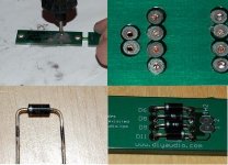
Chas - progress is a 12 guage (2mm) inductor
Rob. That looks nice!
What kind of resistor did you use?
Also, why did you choose 2mm wire over the 1mm that Leach & Jens recommended?
Resistor is an Ohmite 45F10RE 5W Silicone.
I made the inductor out of 2mm wire because
A) I could not find a 1mm enameled wire locally
B) I had this wire left over from an antenna project
C) I was impatient, wanting to propel the whole project forward
D) I was able to get the min # of turns to fit in the allotted space
The bare copper gives it a nice shine. for now...
Jens R51 is the equivalent of R36 in the Leach 4.5. The current through it sets the voltage needed to turn on the output stage.
I'm guessing that Jens added C33 to ensure that the signal was not affected by any potential inductive component in the resistor and keep the two sides of the output seeing the same signal.
I'm guessing that Jens added C33 to ensure that the signal was not affected by any potential inductive component in the resistor and keep the two sides of the output seeing the same signal.
To all,
Where does this Leach amp stand among its peers. It is common knowledge that this is a great amp. But does it equal the Krell's, Pass amps. Maybe a better comparison would be to a Levinson, Rowland since it is class AB. The above mentioned products sell retail for 5000.00 and up. I know personally it is better than any of the Mcintosh amps I USE to own.
Tad
I haven't had a chance to compare to Krell, Levinson or Rowland, but I have compared a Leach to my modified Pass A-75 and a dead bug LM4780 chip amp.
Compared to my Yamaha DSP-A1 that is still used as a pre/pro, no contest. The Yamaha amps sound downright fuzzy in comparison.
The chip amps were a bit better than the Yamaha, but still seemed to lack detail. What were clicks on the chip amps became wood blocks on the Leach.
My A-75 runs on higher voltage rails and a bit less bias than designed. They use 6 IRFP240/9240 pairs biased to about 12W /8R out before going to class AB and the VAS operates in the folded cascode mode. I have four channels of each amp driving a Focal 6W4254/TC120TD5 active XO two way.
Compared to my Leach amps, it is a very close call. I have a slight preference for the A75 which seems to be a bit smoother on the top end with slightly more low level detail.
Of course, I expected the A75 to sound better than the Leach because of its class A operation, not to mention that I put a lot of effort into its enclosure and the test was not blind. There is a distinct possibility that my observations could have been just mirroring my expectations. My then 15 year old son did not hear a difference. He seems to be aware of sound quality, unlike most his age, noticing crossover changes without my prompting him.
When I compared anything to my chip amp the LM3886 chips sound way too bright. I like the detail but it can be a little harsh.
My Leach is on the mellow side. It is very easy to listen too. The Mcintosh Mc2250 was very accurate but lacked some of the Leach midrange detail. There is plenty of punch in both for the bottom end. My hearing is not good enough to make any comparison of the highend. I hope to have my A-75 up and running in the next few months to compare a full on class A sound. The Leach is biased to one amp per rail now. I hope it stays together nothing is getting terrible hot.
Not being able to have a live performance on the left and the amplifier re-creation on the right makes it difficult to make an accurate comparison. It all comes down to what each particular individual prefers.
And thanks for the input. Tad
Use of shunt voltage reference in VAS?
Anyone try using precision shunt voltage references in place of
the zener diodes in the VAS?
A friend recommended using two (10v)LM4040's to replace one 20v zener. That's 8pcs per board...
Good or bad idea?
Any recommendation? I've got some Ero MKC's I was going to use. Tough to fit most 1uf caps in that space.
-Chas
Anyone try using precision shunt voltage references in place of
the zener diodes in the VAS?
A friend recommended using two (10v)LM4040's to replace one 20v zener. That's 8pcs per board...
Good or bad idea?
some report significant improvements in sound quality by choosing a good audio cap for C33.
Any recommendation? I've got some Ero MKC's I was going to use. Tough to fit most 1uf caps in that space.
-Chas
Not a bad idea if you can pull off the flying leads safely. If you use 1% LM4040-10s they will be more stable, quieter and probably accurate enough to not need matching. They should be about a buck for your group - more than zeners, but not a bank breaker.
Cap recommendations I'll leave to more dedicated parts choosers.
Cap recommendations I'll leave to more dedicated parts choosers.
details on diode boards
I just got around to doing this. A small round burr tool seemed to work best for me.
To make sure the diode leads don't protrude, I used a black extra fine Sharpie pen to mark the leads where they protruded from the bottom of the board. I then cut the leads slightly above the marks and soldered them in.
-Chas
I noticed that the Thermal tracking diode PCB's in this latest group buy are plated thru-hole to unmasked pads on the bottom side.
I'll grind the pads off with a Dremel.
I just got around to doing this. A small round burr tool seemed to work best for me.
To make sure the diode leads don't protrude, I used a black extra fine Sharpie pen to mark the leads where they protruded from the bottom of the board. I then cut the leads slightly above the marks and soldered them in.
-Chas
Attachments
Why do you need to do this? Turn the board over and contact the diode BODIES to the heat sink.
Yours may be a fine way to go as well.
Because this is my first scratch-built amp I'm just following the designer's recommendations, since temp compensation is critical to the correct operation of the amp. Plus, Jens shows this orientation on his website.
-Chas
Attachments
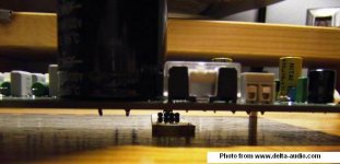
According to Jens the large surface contact of the copper plane(which is tightly fixed to the heatink), plus heat conduction through the copper leads assures good heat transfer.
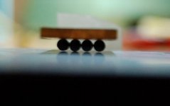
Attached is a photo of the same board with the diodes against the heat sink. Contact area may not be that great due to small variations in the diode bodies, so be sure to use thermal compound. However, you could work the entire assembly against a file or fine sandpaper to file/grind a consistent flat area across all the diode bodies.
I will probably flatten the diodes where they contact the diode PCB on my second amp assembly just to be sure. Just be careful not to overdo it, or the diode could become damaged.
-Chas
Attachments
To all,
Is there anyone who could explain the procedure and exact spec's we are shooting for on this diode circuit. I somewhat understand that we are regulating things for the output with the diode string. What measurements are we shooting for and where do I measure.
This Vb multiplier is a much discussed topic, I just never pick up the information I need on a less learned scale. You know back up a few steps and then start the discussion.
Trying to learn something here. Tad
P.S. Kinda keep it basic.
Practical specs: use standard 1n400x diodes, enjoy.
See the on-semi thermal track thread for a detailed discussion of temperature compensation tips and tweaks.
Nutshell version: As bipolar transistors get hotter they will conduct more at a given Vbe. The compensation circuit tries to match the temperature coefficient to reduce the bias voltage to maintain the same quiescent current.
With four diodes the Leach is a bit overcompensated, with 3 a bit under. Over compensation means that the compensation circuit reduces the Vbe a bit more than required to maintain the bias current. So, as the amp gets hotter the bias is reduced. The danger of under compensation is that if you get the amp hot enough, the output could run away and cook itself. Better a little overcompensated if you can't get perfect compensation.
AndrewT described his testing procedure earlier in this thread IIRC. Set bias with no signal. Run the amp at high power into a load to heat up the output stage. Remove signal. Measure the no signal bias. Ideally it will be the same as the cold value. In an overcompensated Leach it will be a bit lower. Monitor the bias over time to see how it recovers.
Most of us will build with large sinks and operate at low average power, so thermal compensation won't have much impact anyway.
clm811 said:
Yours may be a fine way to go as well.
Because this is my first scratch-built amp I'm just following the designer's recommendations, since temp compensation is critical to the correct operation of the amp. Plus, Jens shows this orientation on his website.
-Chas
There must be some sort of electrical insulation in Jens orientation. Possibly a thermal pad? I would worry about punch through in the pad. You could also mount TO-126 or TO220 transistors (as diodes) on top of the output transistors to thermally couple directly to them, and connect their leads to the diode circuit board.
- Home
- Group Buys
- Jens Rasmussen Leach clone group buy