JMMLC,
I have been looking for your spreadsheet. Can't find it any where.
I am interested in determining if there are particular compression driver types that would work best with the LeCleac'h horns.
In modeling the horn using a "pancake" driver like the JBL2451, where the phase plug ends at the driver's exit opening instead of at inside a deep throat like the JBL2441, would you specifiy a zero degree entrance angle at the throat of the horn?
I now realize that my question in the preceeding post was rather naive. While setting the entrance angle at zero would lengthen the horn (not necessarily a bad thing as the length approaches the wavelength of Fc), it would constrict the entrance angle in such a way as to beam the high frequencies to their detriment. Therefore, there must be an "optimum" entrance angle aside from matching the driver that promotes a desirable coverage angle at high frequencies.
Key: Shape of Wavefront Exiting Phase Plug
Only a catenoidal horn (T=0) after Salmon [1], or the hyperbolic horn of Frehaufer/Geddes [2] matches a slope tangent angle (t=0) of the JBL 2451 driver exit. Here the wavefront at phase plug and driver exit is assumed to be flat disk rather than that of a spherical cap, where (t>0).
[1] Salmon
Scitation: A New Family of Horns
For the Le Cleac’h implementation, the wavefront surface, over which area is calculated, is assumed to be curvilinear rather than plane.
Here the wavefront profile is approximated by a central flat disk [T = 0] or Spherical Cap [T>0] followed by a series of rings having a toroidal surface of decreasing radius of curvature.
[2] Freehafer
Scitation: The Acoustical Impedance of an Infinite Hyperbolic Horn
Here the wave front is assumed to lie on an oblate spheroidal coordinate system. Note that at its apex, the tangent angle (t=0)
To match a horn to an exit tangent angle (t > 0) work from the derivative f’(x) = dy/dx = tan(t) for the horn.
However the slope of the segment resident in the driver body most likely will not follow exactly the locus of the hyperbola of the horn body if it was extended back to the phase plug exit. Thus, the shorter the tapered portion in the driver, the better.
Regards,
WHG
I now realize that my question in the preceeding post was rather naive. While setting the entrance angle at zero would lengthen the horn (not necessarily a bad thing as the length approaches the wavelength of Fc), it would constrict the entrance angle in such a way as to beam the high frequencies to their detriment. Therefore, there must be an "optimum" entrance angle aside from matching the driver that promotes a desirable coverage angle at high frequencies.
Only a catenoidal horn (T=0) after Salmon [1], or the hyperbolic horn of Frehaufer/Geddes [2] matches a slope tangent angle (t=0) of the JBL 2451 driver exit. Here the wavefront at phase plug and driver exit is assumed to be flat disk rather than that of a spherical cap, where (t>0).
[1] Salmon
Scitation: A New Family of Horns
For the Le Cleac’h implementation, the wavefront surface, over which area is calculated, is assumed to be curvilinear rather than plane.
Here the wavefront profile is approximated by a central flat disk [T = 0] or Spherical Cap [T>0] followed by a series of rings having a toroidal surface of decreasing radius of curvature.
[2] Freehafer
Scitation: The Acoustical Impedance of an Infinite Hyperbolic Horn
Here the wave front is assumed to lie on an oblate spheroidal coordinate system. Note that at its apex, the tangent angle (t=0)
To match a horn to an exit tangent angle (t > 0) work from the derivative f’(x) = dy/dx = tan(t) for the horn.
However the slope of the segment resident in the driver body most likely will not follow exactly the locus of the hyperbola of the horn body if it was extended back to the phase plug exit. Thus, the shorter the tapered portion in the driver, the better.
Regards,
WHG
.
However the slope of the segment resident in the driver body most likely will not follow exactly the locus of the hyperbola of the horn body if it was extended back to the phase plug exit. Thus, the shorter the tapered portion in the driver, the better.
Regards,
WHG
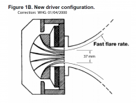
The tapered portion in the driver is very short. See attachment.
Attachments
The tapered portion in the driver is very short. See attachment.
Hello,
As seen in the JBL document, the new driver type can accomodate horns having either a slow flare rate or a rapid alrae rate. That kind of driver will work well with any Le Cléac'h horn.
For sure for my own purpose I always ensure a perfect continuous profile between the compression driver and the horn. This need some DIY.
In the case of a modern driver having a short length between throat between its throat and the apex of the phase plug I generally use simple quadratic law (as at the throat of a Peavey wavegudie... but an OS (@ Geddes) DIY made adaptor can be used too... This will provide a good transformation between the (hypothesised) planar wavefront at the apex of the phase plug to a curved wavefront which will be a bettee fit for the Le Cléac'h horn.
Best regards from Deauville, France
Jean-Michel Le Cléac'h
Last edited:
Hello,
As seen in the JBL document, the new driver type can accomodate horns having either a slow flare rate or a rapid alrae rate. That kind of driver will work well with any Le Cléac'h horn.
For sure for my own purpose I always ensure a perfect continuous profile between the compression driver and the horn. This need some DIY.
In the case of a modern driver having a short length between throat between its throat and the apex of the phase plug I generally use simple quadratic law (as at the throat of a Peavey wavegudie... but an OS (@ Geddes) DIY made adaptor can be used too... This will provide a good transformation between the (hypothesised) planar wavefront at the apex of the phase plug to a curved wavefront which will be a bettee fit for the Le Cléac'h horn.
Best regards from Deauville, France
Jean-Michel Le Cléac'h
Are you saying that with the modern driver of, say 38mm exit, you should provide an adapter to say, a 50mm entry horn, and flare the adapter as quadratic law or OS to match entry angle of horn?
Hello,
As seen in the JBL document, the new driver type can accomodate horns having either a slow flare rate or a rapid alrae rate. That kind of driver will work well with any Le Cléac'h horn.
Hello Jean Michel,
are you sure about this?
From the way I read the JBL document, the recent JBL drivers are named 'rapid flare' for a reason, namely that they were designed so as to have an internal flare rate (due to the phase plug geometry) "double or quadruple" the 'classical' 160Hz.
This seems to me to imply that they would not be optimal for use with slow flare rate horns, no matter what.
Marco
Yes, at double the flair rate of the 160Hz flare, the modern driver would appear to be a good match to a 340Hz horn.
I think (and I await Jean Michael's reponse if I am wrong) that he is trying to create a curved wavefront into the horn throat vs. the planer wavefront at the phase plug exit. However, as this must occur somewhere between the phase plug and the mouth, why the extra adapter? The sooner the better, I presume. But what I am looking for is a driver/horn combination that would not require an adapter.
Yes, at double the flair rate of the 160Hz flare, the modern driver would appear to be a good match to a 340Hz horn.
It might. But in that technical document JBL is not at all clear about whether it's "double" or "quadruple"...
If it's any indication, the phaseplug of JBL's 435Be driver (which was used in the then-flagship K2 S9800 loudspeaker system) has an expansion rate corresponding to an interal Fc = 550Hz (http://test.audioheritage.org/Web_P..._of_JBL/06_Second_Harman_Era/SHE_Content.html).
I do not know if all modern 'rapid flare' drivers share the exact same Fc, but 550Hz would certainly be too high to be a good match for a 340Hz horn.
Marco
Last edited:
It might. But JBL is not clear about whether it's "double" or "quadruple"...
Yep. It sure would be nice to get a clear answer on that. I hope someone at JBL might know. That phase plug is said to be a better design at high frequencies, too. Haven't seen any details on that plug, either. Just marketing hype. I wonder if they have a patent on it. And by flare rate, I am referring very loosely to both Fc and expansion (i.e., exponential, hyperbolic, etc.).
Perhaps I am making muchado about nothing and these effects are not that sonically significant.
Last edited:
Hello Jean Michel,
are you sure about this?
From the way I read the JBL document, the recent JBL drivers are named 'rapid flare' for a reason, namely that they were designed so as to have an internal flare rate (due to the phase plug geometry) "double or quadruple" the 'classical' 160Hz.
This seems to me to imply that they would not be optimal for use with slow flare rate horns, no matter what.
Marco
Hello Marco,
In the JBL document the only difference we can see between the rapid flare CD type and the slow flare CD type is the length of the outlet, very long in the case of the slow flare and very short for the rapid flare. All other features of the drivers are similar (phase plug, etc...)
Old type drivers could not be used with waveguides because those one require to have a rapid flare at throat (to be able to cover a larger radiation angle in a large interval of frequency). If you used such old driver on a waveguide you have a lot of diffraction at the disontunity between the driver outlet and the throat of the waveguide. That's why the new CD type have a shorter outlet.
And also that's why, e.g., I prefer to use my beloved Yamaha 6681A without the large adaptor part which is used to screww the horn to the driver but which, while looking as a large alnico magnet is hollow and useless; Removing that front adaptor part you have an outlet in the plane of the apex of the phase plug and the driver is most similar to a modern "rapid flare" compression driver.
In fact while said to provide a planar wavefront at their outlet most compression drivers fail to do that. Even if the figured JBL driver is said to have a 0° angle at throat and can be adapted to a horn having a 0° angle at throat, continuity of the expansion law of the wavefronts is not obtained beacause of the internal flare of the ducts of the phase plug themselves...
Best regards from Deauville, France
Jean-Michel Le Cléac'h
I assume the old JBL phase plug had an exponential expansion in line with the power response adapted to maintain a flat on-axis frequency response into an exponential horn that would compensate for mass rolloff.
But the new design is designed with CD horns in mind, so I'm not sure how the expansion goes in the modern plugs.
But the new design is designed with CD horns in mind, so I'm not sure how the expansion goes in the modern plugs.
Hello Marco,
In the JBL document the only difference we can see between the rapid flare CD type and the slow flare CD type is the length of the outlet, very long in the case of the slow flare and very short for the rapid flare. All other features of the drivers are similar (phase plug, etc...)
Old type drivers could not be used with waveguides because those one require to have a rapid flare at throat (to be able to cover a larger radiation angle in a large interval of frequency). If you used such old driver on a waveguide you have a lot of diffraction at the disontunity between the driver outlet and the throat of the waveguide. That's why the new CD type have a shorter outlet.
And also that's why, e.g., I prefer to use my beloved Yamaha 6681A without the large adaptor part which is used to screww the horn to the driver but which, while looking as a large alnico magnet is hollow and useless; Removing that front adaptor part you have an outlet in the plane of the apex of the phase plug and the driver is most similar to a modern "rapid flare" compression driver.
In fact while said to provide a planar wavefront at their outlet most compression drivers fail to do that. Even if the figured JBL driver is said to have a 0° angle at throat and can be adapted to a horn having a 0° angle at throat, continuity of the expansion law of the wavefronts is not obtained beacause of the internal flare of the ducts of the phase plug themselves...
Best regards from Deauville, France
Jean-Michel Le Cléac'h
About the JA6681B. I read the short reviw of it by the guy behind the hifiheroin blog and he wrote that he understands what people like in the speaker but it cannot compare tk the very best, but that this would be unfair. What is your opinion, since you must have heard the best drivers out there by now?
Last edited:
And also that's why, e.g., I prefer to use my beloved Yamaha 6681A without the large adaptor part which is used to screww the horn to the driver but which, while looking as a large alnico magnet is hollow and useless; Removing that front adaptor part you have an outlet in the plane of the apex of the phase plug and the driver is most similar to a modern "rapid flare" compression driver.
Jean-Michel Le Cléac'h
Hello Jean-Michel,
What would you estimate the flare rate of the JA6681A/B (there was an "A" version? I suppose that makes sense!) to be with the hollow casting removed?
Best regards and thank-you,
cv
Jean-Michel,As seen in the JBL document, the new driver type can accomodate horns having either a slow flare rate or a rapid alrae rate. That kind of driver will work well with any Le Cléac'h horn.
For sure for my own purpose I always ensure a perfect continuous profile between the compression driver and the horn. This need some DIY.
In the case of a modern driver having a short length between throat between its throat and the apex of the phase plug I generally use simple quadratic law (as at the throat of a Peavey wavegudie... but an OS (@ Geddes) DIY made adaptor can be used too... This will provide a good transformation between the (hypothesised) planar wavefront at the apex of the phase plug to a curved wavefront which will be a bettee fit for the Le Cléac'h horn.
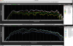
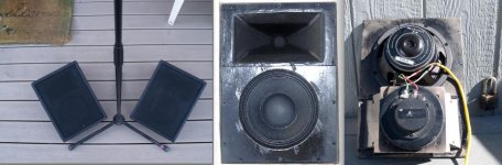
Having used the quadratic throat on 90 X 20 and 90 x 45 degree conical horns with both the Eminence PSD2002 "pancake" and old style long JBL 2420, HF dispersion was similar for either, the JBL maintaining -6 at 45 degree off at 10kHz, -8 at 16kHz.
The PSD 2002 has such ragged frequency response above 12 kHz it is a bit hard to discern HF dispersion, but had them laying around and wanted to make some tiny floor monitors...
Ensuring a perfect continuous profile between the compression driver and the horn seems to be far more important than the exit geometry of the driver.
Art
Attachments
None of the drivers I have worked with are easily removed, though there may be some types that are.are the phase plugs easily removed for experimenting?
Experimenting can be fun, what do you hope to accomplish that the designers didn't?
hello, i have not worked alot with compression drivers.
are the phase plugs easily removed for experimenting?
I am thinking of 3D printer which might make a interesting phase plugs for experimentation.
They are not easily removed. In the older JBLs, you would have to demagnetize them to take them apart. I believe the plugs are press fit. Then they would have to be reassembled and remagnetized. It takes some serious equipment to magnetize them, and the only place(s) I could find to do this in the USA is on the west coast.
It would be interesting to fabricate them with 3d printing, but due to the effort to change them out, it seems like you'd want to have a firm design in mind to do it once. If you are so inclined, you might want to consider reading Earl Geddes patent, which is in the public domain.
Attachments
Correction
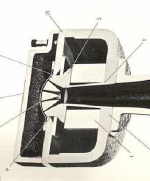
The driver section figures in the JBL specification [2] are incorrectly drawn. See attached figure [1] for the correction. The phase plug and driver exits coincide. The passage slope angle at that point is (t=0).
For optimum performance, try a Freehafer neck joined to a Le Cleac’h bell.
Regards,
WHG
The tapered portion in the driver is very short. See attachment.
The driver section figures in the JBL specification [2] are incorrectly drawn. See attached figure [1] for the correction. The phase plug and driver exits coincide. The passage slope angle at that point is (t=0).
For optimum performance, try a Freehafer neck joined to a Le Cleac’h bell.
Regards,
WHG
Attachments
- Home
- Loudspeakers
- Multi-Way
- Jean Michel on LeCleac'h horns