to panomaniac
Christophe
have you seen my post? you can get the spreadsheet therePS the file isn't on the site pointed by J-Mbut I can be found there, in French : Téléchargement gratuit
Christophe
Hello Panomaniac,
May be you had the same problem as was decribed in
http://www.diyaudio.com/forums/multi-way/154447-how-build-large-round-front-horns-7.html#post2105758
See my reply and following messages to this post.
Also give a look to:
http://www.diyaudio.com/forums/multi-way/140190-jean-michel-lecleach-horns-78.html#post2180157
(in short: better to begin to glue by the mouth end of the horn, not by the throat...)
Best regards from Paris, France
Jean-Michel Le Cléac'h
Salut J-M. I think the version I have allows only round or square horns. I tried a small scale version of a 4 side horn. Joining the 4 sides togeher is very strange. Perhaps I should make a photo of the model.
Dispersion across frequency range for large LeCleach flared horn?
Hi Jmmcl,
Does there exist any spreadsheet or equivalent in order to calculate the dispersion across the frequency range for a large 160 or 200 Hz LeCleach flared horn with a 2” throat?
I ask because I consider using a large LeCleach flared low-mid horn for the mid-range and wants to mate it with a Beyma TPL-150H tweeter in the 1300-2000 Hz range. The Beyma TPL-150H has a constant horizontal dispersion of 80 degrees, and if possible I would like to match the horizontal dispersion between the two horns around the crossover frequency.
PS: I apologize if this information has already been revealed in this thread.
Thanks a lot!
Best regards
Peter
hi Peter
i would use a tractrix horn with less rapid opening. That will load your compression driver better, aloud getting more output in the lower range.
Hornresp will calculate this, iirc. Generally I doubt you'll get that wide of directivity from a large LC horn at the top end of its bandwidth. In the course of doing lots of simulations, I've found that it is possible to match the directivity of a tweeter to a LC mid horn, but it will be fairly narrow directivity. However if you use the LC horn over a more limited bandwidth - say a decade or less - then it could be possible. I was looking at an example that looks like it would be close for a 275hz LC horn.
However note that because the TPL150H does not have symmetric radiation while the LC horn would, the power response could still be a bit funky when you cross from the mid to the tweeter even if you've matched the horizontal directivities. I'm not sure how much that would matter perceptually with these devices that have a more controlled directivity though.
However note that because the TPL150H does not have symmetric radiation while the LC horn would, the power response could still be a bit funky when you cross from the mid to the tweeter even if you've matched the horizontal directivities. I'm not sure how much that would matter perceptually with these devices that have a more controlled directivity though.
Hornresp will calculate this, iirc. Generally I doubt you'll get that wide of directivity from a large LC horn at the top end of its bandwidth. In the course of doing lots of simulations, I've found that it is possible to match the directivity of a tweeter to a LC mid horn, but it will be fairly narrow directivity. However if you use the LC horn over a more limited bandwidth - say a decade or less - then it could be possible. I was looking at an example that looks like it would be close for a 275hz LC horn.
However note that because the TPL150H does not have symmetric radiation while the LC horn would, the power response could still be a bit funky when you cross from the mid to the tweeter even if you've matched the horizontal directivities. I'm not sure how much that would matter perceptually with these devices that have a more controlled directivity though.
Hi John,
Thanks for responding! I have an old version of HornResp (v 19.20), and I do not think it is possible to predict dispersion with this version. I just tried to download the newest version via this link:
Telstra BigBlog -
But for some reason (!?) I cannot activate any downloading (maybe I have to be a member of BigBloc in order to get access!?)
I feared that the dispersion would be pretty narrow around in the 1300-2000 Hz range in a big horn.
One way to get 80 degree horizontal dispersion with a big LeCleach flared horn might be to make a horn with two straight sides positioned in a 80 degree angle, and then only let the "top" and "bottom" side of the horn be curved in accordance to the calculated curvature!?
Angelo: yes a tractrix would be another option, but it will probably run into just about the same issues with regards to dispersion.
Best regards
Peter
I've previously been able to download from there but now I can't either. Maybe David took the link down while he's working on a glitch in the newest release? I currently have v27 and you can calculate beamwidth, polar pattern, response at any angle and a polar map for a LC horn. If you can't get it downloaded soon, email me and I can send you v27.
Yes, you could make a horn like you suggest but unless you flaired those walls at the mouth and put the correct transition at the throat, you would probably do more harm than good. Then depending on how you handled the vertical expansion, that could create a host of other issues.
Yes, you could make a horn like you suggest but unless you flaired those walls at the mouth and put the correct transition at the throat, you would probably do more harm than good. Then depending on how you handled the vertical expansion, that could create a host of other issues.
I've previously been able to download from there but now I can't either. Maybe David took the link down while he's working on a glitch in the newest release? I currently have v27 and you can calculate beamwidth, polar pattern, response at any angle and a polar map for a LC horn. If you can't get it downloaded soon, email me and I can send you v27.
Yes, you could make a horn like you suggest but unless you flaired those walls at the mouth and put the correct transition at the throat, you would probably do more harm than good. Then depending on how you handled the vertical expansion, that could create a host of other issues.
Hi John,
Thanks a lot for the kind offer! However, the link will probably be working again pretty soon, so I will give it a few days...
With regards to my suggestion and your comment, I know that many things can go wrong - it was just one suggestion of getting dispersion patterns to match. One guy at ebay sells machine crafted metal throat transitions that may be a good starting point for a horn with a rectanglar throat.
Best regards
Peter
I've previously been able to download from there but now I can't either.
Hi John,
My BigBlog site crashed on Sunday July 25. The problem has been reported to my Internet Service Provider.
Kind regards,
David
Hi John,
My BigBlog site crashed on Sunday July 25. The problem has been reported to my Internet Service Provider.
Kind regards,
David
Thanks a lot for the information, David - and thanks for a great piece of software!
Best regards
Peter
Hi Peter and John,
The new Hornresp website address is as shown below.
Kind regards,
David
Thanks a lot!
Best regards
Peter
Azura425
I wonder why the new Azura425 horn measures so poorly?
.
http://www.diyaudio.com/forums/multi-way/100392-beyond-ariel-721.html#post2274681
.
Frequency Response - drivervault
I wonder why the new Azura425 horn measures so poorly?
.
http://www.diyaudio.com/forums/multi-way/100392-beyond-ariel-721.html#post2274681
.
Frequency Response - drivervault
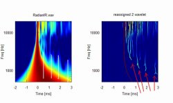
First off, do not forget that wavelet analysis is quite a magnification glass - not really a tool of mercy - so no wonder wavelet analysis is banned by most audiofools.
And also don't forget that we have to distinguish what comes from the "horn" (Azurahorn in our case) and what comes form elsewhere.
Wavelet analysis does not care where the reflections are coming from - its just displayed and its our part to make some meaning out of it.
On Elias' plots we see heavy contamination on the top frequency range at short delay times. This is most likely not from the Azuahorn itself but from within the compression driver or from a mismatch between driver contour and Azurahorn contour at the joint (or more precisely: wavefront mismatch).
And finally do not forget that a (any !) horn starts out right at the diaphragm - and not at the joint of the compression driver - as most people assume!!!
This means that design of phase plug and matching to the "horn" is as crucial as the "horn" itself - at least if you are looking at the very details.
An as a PS regarding your question on extending the contour by a foam roll - I think at least regarding the department I was referring to - I see little chance for improvement from you suggestion - as the cause is elsewhere IMO
Michael
Last edited:
Pipe foam
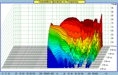
The hash above 10KHz looks like a mismatch at the driver interface or just the poor performance of the driver and is easily seen in a common CSD of the GPA/Altec 288-16H on that horn as well as the wavelet transform of the Radian 745. Is the entry a little too small or is it just the drivers?
My recomendation of using pipe foam
McMaster-Carr
catalog page 3485,
is aimed at reducing the hot spots that are seen at .6ms intervals below 2KHz.The pipe foam could be a simple way to add a more complete spiral flair back to any baffle-less horn in order to reduce standing waves from the mouth termination.
First off, do not forget that wavelet analysis is quite a magnification glass - not really a tool of mercy - so no wonder wavelet analysis is banned by most audiofools.
And also don't forget that we have to distinguish what comes from the "horn" (Azurahorn in our case) and what comes form elsewhere.
Wavelet analysis does not care where the reflections are coming from - its just displayed and its our part to make some meaning out of it.
On Elias' plots we see heavy contamination on the top frequency range at short delay times. This is most likely not from the Azuahorn itself but from within the compression driver or from a mismatch between driver contour and Azurahorn contour at the joint (or more precisely: wavefront mismatch).
And finally do not forget that a (any !) horn starts out right at the diaphragm - and not at the joint of the compression driver - as most people assume!!!
This means that design of phase plug and matching to the "horn" is as crucial as the "horn" itself - at least if you are looking at the very details.
An as a PS regarding your question on extending the contour by a foam roll - I think at least regarding the department I was referring to - I see little chance for improvement from you suggestion - as the cause is elsewhere IMO
Michael
Attachments
- Home
- Loudspeakers
- Multi-Way
- Jean Michel on LeCleac'h horns