hello, I am new on this thread and I have to start from a basic point.
I would like to find the excel files about the JeanMichel Le Cleach'h forn formulas with a short explanation about how they works.
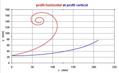
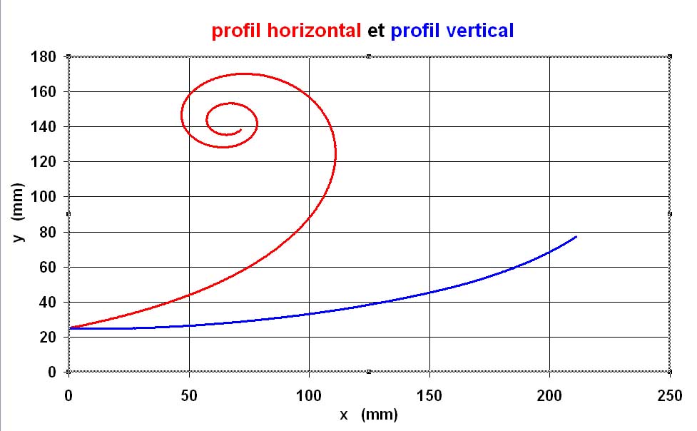
I downloaded two excel sheets but I am not shure about the way to read the results. The horizontal and the vertical profiles stop at 2 different distances from the source. Does it mean I have the vertical parts longer than the horizonatal one? And the horizontal profile closes on a curl and the vertical one don't. Why the vertical one doesn't go to end with a curl.
I scare I don't read clearly the results.
More, where can I find the formulas for the round section horns?
Last, I promis, how is possible, in a controlled dispersion horn, to avoid the 90° angle between the vertical and horizontal? do the Poland guys use a formula or they filled only the angles and make the horn longer (cause the loose of volume)? Any idea? How to make a model for the elliptical JMLC or the elliptical Iwata 300Hz? How link the vertical and horizontal profiles?
Thanks for any help or any link to the pages where I can understand more.
Ciao
I would like to find the excel files about the JeanMichel Le Cleach'h forn formulas with a short explanation about how they works.
I downloaded two excel sheets but I am not shure about the way to read the results. The horizontal and the vertical profiles stop at 2 different distances from the source. Does it mean I have the vertical parts longer than the horizonatal one? And the horizontal profile closes on a curl and the vertical one don't. Why the vertical one doesn't go to end with a curl.
I scare I don't read clearly the results.
More, where can I find the formulas for the round section horns?
Last, I promis, how is possible, in a controlled dispersion horn, to avoid the 90° angle between the vertical and horizontal? do the Poland guys use a formula or they filled only the angles and make the horn longer (cause the loose of volume)? Any idea? How to make a model for the elliptical JMLC or the elliptical Iwata 300Hz? How link the vertical and horizontal profiles?
Thanks for any help or any link to the pages where I can understand more.
Ciao
Attachments
Hello,
The spreadsheets to calculate by my own method the non axisymetrical horns pictured on :
http://www.diyaudio.com/forums/atta...4362-jean-michel-lecleach-horns-audio_en7.gif
are very large (more than 100 megaoctets ). That's why I cannot nor send them attached to an email nor to a message in such forums. To perform his 3D drawings for the different horns and the CAO programmation, J. Zagaja used cloud of points (3D coordinates) that I calculated for him.
The other graph you show in your message:
http://www.diyaudio.com/forums/atta...an-michel-lecleach-horns-hrz-vrt-profiles.jpg
is an output of my Iwata spreadsheet. This is my attempt to the calculation of the classical Iwata horn you can see there:
http://i307.photobucket.com/albums/nn281/AudioVoice/Iwata_3.jpg
http://i307.photobucket.com/albums/nn281/AudioVoice/AvDAO.jpg
But the "quasi Iwata horn" you can see on bottom left corner of the picture:
http://www.diyaudio.com/forums/atta...4362-jean-michel-lecleach-horns-audio_en7.gif
is different, and is a full design of mine . I only retain from the original Iwata design the evolution from the throat to the mouth of the ratio width/height and the T = 0.5 coefficient in the expansion law.
You may find some early descriptions of the Le CLéac'h horn at
lecleach
and on the same webpage you can find the spreadsheet for the calculation of the original axisymetrical Le Cléac'h horn
http://nicolas.davidenko.perso.sfr.fr/outils/axial.zip
(I didn't verify if this is an old or newer version of the spreadsheet. The recents version allow a shape with petals like facets.)
There is also a spreadsheet for the calculation of quasi cylindrical waves Le Cléac'h basshorns at
http://nicolas.davidenko.perso.sfr.fr/outils/cylind.zip
Best regards from Paris, France
Jean-Michel Le Cléac'h
hello, I am new on this thread and I have to start from a basic point.
I would like to find the excel files about the JeanMichel Le Cleach'h forn formulas with a short explanation about how they works.
I downloaded two excel sheets but I am not shure about the way to read the results. The horizontal and the vertical profiles stop at 2 different distances from the source. Does it mean I have the vertical parts longer than the horizonatal one? And the horizontal profile closes on a curl and the vertical one don't. Why the vertical one doesn't go to end with a curl.
I scare I don't read clearly the results.
More, where can I find the formulas for the round section horns?
Last, I promis, how is possible, in a controlled dispersion horn, to avoid the 90° angle between the vertical and horizontal? do the Poland guys use a formula or they filled only the angles and make the horn longer (cause the loose of volume)? Any idea? How to make a model for the elliptical JMLC or the elliptical Iwata 300Hz? How link the vertical and horizontal profiles?
Thanks for any help or any link to the pages where I can understand more.
Ciao
thanks for your support. I will study those spreadsheet.
I would like to make a wood elliptical horn. I work in the mould field and for sure I can find some workshop can make for me, but they need the mathematics so the guys can program the CNC machine (.stp or .igs file).
The CNC machine can work on a very big brick, 2000x4000x2000. Usually they make the counterweight of the sailboats, tungsten or magnesium (Luna Rossa, Mascalzone Latino, Moro).
Can you help me on this? by FTP?
Thanks in any case, even if it is no possible.
Regards from Venice - Italy. Mario Canever.
Hello Mario,
I am living Paris for several days and I'll be back on monday 28.
Please,would you contact me on June 28th or later.
Best regards from Paris, France
Jean-Michel Le Cléac'h
I am living Paris for several days and I'll be back on monday 28.
Please,would you contact me on June 28th or later.
Best regards from Paris, France
Jean-Michel Le Cléac'h
Can you help me on this? by FTP?
Thanks in any case, even if it is no possible.
Regards from Venice - Italy. Mario Canever.
To Sendler or others. The calculation file on the ndavidenko site seems to be an old file created on 12/2001. It does not provide the calculation for mutli petal horns and does not correspond to explanation given by Jean-Michel. And I know French. Can anybody point me a site with the right file or post it here or send it to me by email please ?
Chris
Chris
Ok guys I founded it with Google:
www.eflatjump.se/JMLC.xls
To Jean-Michel, the site of Ndavidenko you point regularly for the source of your calculation file contains only the axisymetric round and square version of the file (12/2001). Maybe your friend can add the file for the petal horns on his site ?
Christophe
www.eflatjump.se/JMLC.xls
To Jean-Michel, the site of Ndavidenko you point regularly for the source of your calculation file contains only the axisymetric round and square version of the file (12/2001). Maybe your friend can add the file for the petal horns on his site ?
Christophe
Last edited:
Ok guys I founded it with Google:
www.eflatjump.se/JMLC.xls
Hey Christophe,
That is on my bands ftp that I thought was only for me
 . But the spreadsheet is to be found on a some french site.
However there is a new modified spreadsheet. Think you should ask Jmmlc for a copy.
About the speadsheet: Is the "Acoustical cut-off frequency" the lowest usable frequency or is it the theoretical calculated frequency of the horn?
Oups !
Sorry if I abused of your bandwith, but you know it was on Google, so I thought it free to pick sa usual.
Will ask Jean-Michel when he comes back. Thanks for pointing that
Christophe
PS the file isn't on the site pointed by J-M but I can be found there, in French : http://petoindominique.fr/php/charger.php
PS2 as I understand the cut-off frequency is the frequency of the horn, the Fc
Sorry if I abused of your bandwith, but you know it was on Google, so I thought it free to pick sa usual
.Will ask Jean-Michel when he comes back. Thanks for pointing that
Christophe
PS the file isn't on the site pointed by J-M
but I can be found there, in French : http://petoindominique.fr/php/charger.phpPS2 as I understand the cut-off frequency is the frequency of the horn, the Fc
Last edited:
how to control the dispersion, vertical and horizontal
Dear Jean-Michel,
I studied the spreadsheed and understood your expansion way. Thanks to Nicolas Davidenko (he has to invert the X and Y on the graph of the circular horn - the label only) and Kolbrek.
How is possible to control the dispersion? W parameter? Do you follow a law to continuosly make it variables for the vertical to the horizontal plane?
And, I am curios, what's the idea at the beginning that suggested you to set up your expansion way? Do you know if something in the nature spreads like your expansion horn? Seems so "natural" your idea.
Thanks for your attention.
Mario Canever - Regards from Venice - Italy
Hello Mario,
I am living Paris for several days and I'll be back on monday 28.
Please,would you contact me on June 28th or later.
Best regards from Paris, France
Jean-Michel Le Cléac'h
Dear Jean-Michel,
I studied the spreadsheed and understood your expansion way. Thanks to Nicolas Davidenko (he has to invert the X and Y on the graph of the circular horn - the label only) and Kolbrek.
How is possible to control the dispersion? W parameter? Do you follow a law to continuosly make it variables for the vertical to the horizontal plane?
And, I am curios, what's the idea at the beginning that suggested you to set up your expansion way? Do you know if something in the nature spreads like your expansion horn? Seems so "natural" your idea.
Thanks for your attention.
Mario Canever - Regards from Venice - Italy
Hello Mario,
Most of the answers are in the message:
http://www.diyaudio.com/forums/multi-way/140190-jean-michel-lecleach-horns.html#post1770248
In fact as I said in that message rather than a new expansion (or a new profile), my method has to be considered as a new method to calculate horns when we know how the area of the wavefronts evolves when travelling along the horn . The original thing in my method is that the shape of the wavefronts is not chosen arbitrarly in a fist step (wavefronts are nor spherical nor plans...) but only obeys to rules which many considers as "natural":
1) the wavefront at step t(i) is parallel/equidistant to the wavefront at time t(i-1).
2) the wavefronts are orthogonal to the walls of the horn.
Most Le Cléac'h horns are calculated with expansion laws considered as (partial) solution of the Webster the most common being hypex with T = 0.707 which one generally leads to a most resitive acoustical impedance curve inside a very wide interval of frequency.
IMHO acoustical loading of a compression driver (or a low Qts loudspeaker ) is benefitial to the sound. And that's where exponential or hypex are superior to other expansions.
Then in the last years due to intense marketing and lobbying from JBL and other commercial contenders more interest has been given to constant directivity horns (and waveguides). In fact most loudspeakers systems described as constant directivity only possess constant directivity behaviour over 1000Hz (or so) and IMHO their drawbacks (diffraction due to rapid profile variations, reflections from the mouth to the throat, more influence of HOMs due to a rapid variation of the tangential angle near the throat) are not equilibrated by the benefits of the CD (comfort of a wider listening area...).
But we are few, hoping that in the future the best of 2 worlds could be gathered: acoustic loading, low diffraction of the Le Cléac'h horns + CD. Some work has been done on such way (studies by Mige0 , Soongsc and myself).
The most advanced shape at the moment is IMHO Mige0's "Minphase" horn.
Best regards from Paris, France
Jean-Michel Le Cléac'h
How is possible to control the dispersion? W parameter? Do you follow a law to continuosly make it variables for the vertical to the horizontal plane?
And, I am curios, what's the idea at the beginning that suggested you to set up your expansion way? Do you know if something in the nature spreads like your expansion horn? Seems so "natural" your idea.
Last edited:
It does seem the hyperbolic loading can be tuned to provide a fairly flat acoustic impedance.Hello Mario,
...
IMHO acoustical loading of a compression driver (or a low Qts loudspeaker ) is benefitial to the sound. And that's where exponential or hypex are superior to other expansions.
...
But we are few, hoping that in the future the best of 2 worlds could be gathered: acoustic loading, low diffraction of the Le Cléac'h horns + CD. Some work has been done on such way (studies by Mige0 , Soongsc and myself).
The most advanced shape at the moment is IMHO Mige0's "Minphase" horn.
Best regards from Paris, France
Jean-Michel Le Cléac'h
I am quite interested in seeing more information on Mige0's "Minphase" horn, CSD and polar plots in small increments up to 45 deg. However, these do not seem to be available.
Hello Soongsc,
For bass horns and for horns having to reproduce a very interval of frequency I always recommanded T = 0.
I doubt I have been followed though as the axial length of the horn is enlarged.
But users of Hornresp can simulate a Le Cléac'h horn having T = 0 and compare with T = 1 (e.g.).
Here attached the compared simulated response of T =0.0 and 0.8 Le Cléac'h horns.
The only negative point I see with R = 0.0 is a rise of the group delay at the acoustical cut-off frequency (but for bass horn having Fc < 50Hz this is not audible).
Best regards from Paris, France
Jean-Michel Le Cléac'h
]
It does seem the hyperbolic loading can be tuned to provide a fairly flat acoustic impedance.
I am quite interested in seeing more information on Mige0's "Minphase" horn, CSD and polar plots in small increments up to 45 deg. However, these do not seem to be available.
Attachments
Jean-Michel, Up to now, I have not studied low frequency horns, but I do intend to do so. Studying of some papers, it does seem that the polar profile benefits reproduction of image focus. I am quite interested in figuring out a way to implement this in a normal living environment.
Hello,
You probably know that my friend Marco Henry was the first builder of Le Cléac'h horns. It begun to make them for the DIY crowd in 1998 and sold them under the label "Musique Concrète".
Since few years he was developping with few friends (Hugues Borsarello being one of the major technical contributor) a complete enclosure that they could consider as their masterpiece.
The final product's name is "La Grande Castine" (castine being the name of the female inhabitants of Saint-Cast in Brittany where Marco is living).
Srajan Ebaen used to audition "La Grande Castine" and he published his impressions on his 6Moons website:
6moons industry features: La Grande Castine
All the horns used in "La Grande Castine are Le Cléac'h horns" (the bass horn being somewhat truncated though).
As the acoustical cut off of the bass horn is a bit high, a dipole Infraplanar subwoofer commercialized by Claude Lacroix and Jean-Yves Soria has been used below 80Hz.
Best regards from Paris, France
Jean-Michel Le Cléac'h
Angle de sortie
Hello Jean-Michel,
A while ago I received a copy of your latest spreadsheet. Will now build a horn.
Using JBL 2441 or 2482 they both share a ca 70mm long horn part in the driver. How should one design the horn? from the phase plug or from the aperture of thr driver?
Also how should the "output angle of the compression driver" be chosen and defined? Should this be the measured angle at one side of the driver or both sides added with ref to the longitude of the horn(sorry my English isn´t good enough to desrcibe it better)? Also how important is it, going from zero degrees and up?
Can you also describe in what way the new calculation is better the old?
Thanks!
Hello Jean-Michel,
A while ago I received a copy of your latest spreadsheet. Will now build a horn.
Using JBL 2441 or 2482 they both share a ca 70mm long horn part in the driver. How should one design the horn? from the phase plug or from the aperture of thr driver?
Also how should the "output angle of the compression driver" be chosen and defined? Should this be the measured angle at one side of the driver or both sides added with ref to the longitude of the horn(sorry my English isn´t good enough to desrcibe it better
)? Also how important is it, going from zero degrees and up?Can you also describe in what way the new calculation is better the old?
Thanks!
Hello,
The 70mm part "inside the driver" you mention should be considered as belonging to the horn. I don't know the value of the output angle of the JBL drivers. Here are the (double) output angle for various compression drivers.
18sound:
NSD1095N, ND1090 = 27°
NSD1480N = 10°
B&C
1"
DE250 14.6°
DE10 7.7°
DE12 24°
DE400TN 20.7°
DE400 31°
DE500 17°
DE200 9.9°
2"
DE85TN 34.5°
DE750TN 22°
DE950TN 17°
BEYMA:
CP750Nd – 24º
CP850Nd – 7º
CP755Nd – 12º60’
SMC65Nd – 15º
CP385Nd – 16º30’
SMC225Nd – 13º1’
In the version of the spreadsheet using the output angle, t
The angle at throat of the horn should be the same as the measured output angle of the driver but this is a limitation versus the acoustical frequency.
It is better to input the angle value if you know it, if not a value of 5 to 7.5 degrees should be OK but in fact, in this version of the spreadsheet, there is few influence of that angle on most part of the horn profile.
In the case the output angle of the driver is very different of the throat angle of the horn, the calculation will induce some ripples in the profile at throat and that's a problem for CNC machining (but those ripples are nearly invisible from some distance from the throat and if you don't use CNC genarlly that's not a problem).
I wrote one year ago a more recent version of the spreadsheet that allow some spleen adaptation between a driver having an output angle very different than the throat angle of the horn (which depends on Fc). It allows to use Le Cléac'h horns with those modern drivers having large output angle, with a smooth transition at throat. For the moment that version was not public (as I don't have any website myself...)
The main difference between the newest public version of the spreadsheet and the original version is that the iterative estimation of the curvilinear width at each distance from the throat is more reliable (this is also the way Hornresp calculate Le Cléac'h horn.
Best regards from Paris, France
Jean-Michel Le Cléac'h
A while ago I received a copy of your latest spreadsheet. Will now build a horn.
Using JBL 2441 or 2482 they both share a ca 70mm long horn part in the driver. How should one design the horn? from the phase plug or from the aperture of thr driver?
Also how should the "output angle of the compression driver" be chosen and defined? Should this be the measured angle at one side of the driver or both sides added with ref to the longitude of the horn(sorry my English isn´t good enough to desrcibe it better
Can you also describe in what way the new calculation is better the old?
Inside driver
Hello again,
If using the inside of the driver we will maybe have a problem. According to my calculations the short horn inside have an exponential flare of 160Hz. Doesn´t this give a hump going from the driver to your horn if we chose another Fc.
If I understand you right we should calculate with "the (double) output angle" cut in the two. This might be obvious but I have to doublecheck.
Ran your old and 200/38/4/0,8 gave 23,5 radius at 70mm
200/38/4/1 gave the optimal 24,5mm
The 70mm part "inside the driver" you mention should be considered as belonging to the horn. I don't know the value of the output angle of the JBL drivers. Here are the (double) output angle for various compression drivers
Hello again,
If using the inside of the driver we will maybe have a problem. According to my calculations the short horn inside have an exponential flare of 160Hz. Doesn´t this give a hump going from the driver to your horn if we chose another Fc.
If I understand you right we should calculate with "the (double) output angle" cut in the two. This might be obvious but I have to doublecheck.
Ran your old and 200/38/4/0,8 gave 23,5 radius at 70mm
200/38/4/1 gave the optimal 24,5mm
Last edited:
- Home
- Loudspeakers
- Multi-Way
- Jean Michel on LeCleac'h horns