Something like this then?
531202B02500G Aavid Thermalloy | Mouser
and
1446622 Silicone Heat Sink Compound Lubricant Grease, 5 oz., 140 g Tube: Industrial Lubricants: Amazon.com: Industrial & Scientific
531202B02500G Aavid Thermalloy | Mouser
and
1446622 Silicone Heat Sink Compound Lubricant Grease, 5 oz., 140 g Tube: Industrial Lubricants: Amazon.com: Industrial & Scientific
Last edited:
That's a big one, 2 inches tall. If you have the space within the enclosure, then I'm sure that would work great. I think you can use a 1 inch tall one and be fine. The bigger one will cool more effectively (more surface area). I don't have the engineering chops to calculate how much heat dissipation is actually needed here.
That heatsink is designed to be mounted into holes (pads) on a PCB.
--
That heatsink is designed to be mounted into holes (pads) on a PCB.
--
Oh man I'd have to dig out my old thermo text for that. IIRC with a parallel finned sink and natural convection there's a simplified case to use so you don't have to dive into Nusselt and Rayleigh. Well....in their complex forms anywho 
I'm guessing for just 10W of P,diss you'll be fine with a 1-1.5" package.
I'm guessing for just 10W of P,diss you'll be fine with a 1-1.5" package.
more area, more better
more air! more better as well.
Generally the ruler for heatsinks is (*C/W)
so a 10 c/w would get 10*C hotter than surrounding air for every 1W of dissipation. Lower number means the sink works better.
Since you're around ~10W of P,diss lets also assume that you're at 25C ambient, so you've only got about 125*C to work with MAX (graphs only go up to 150*C). This gives you a minimum c/w on the heatsink of 12.5.
I wouldn't take it much higher than about 7.5, after that your output voltage starts to deviate. Here's one that's 3.5 which would work pretty well.
TO-220 heatsink
While we're on the subject of heatsinks... Here's a question: If you take a TO-220 package and heatsink it to a strip of L-channel aluminum that's about 2 inches tall, what's the approximate C/W rating you'd expect? I was thinking something like this:

Crown Bolt 3/8 in. W x 1/2 in. H x 48 in. L x 1/8 in. Thick Aluminum Trim Channel-42530 - The Home Depot
Sorry if this is taking the thread off-topic. You can tell me to take it elsewhere, it's OK.
--
Crown Bolt 3/8 in. W x 1/2 in. H x 48 in. L x 1/8 in. Thick Aluminum Trim Channel-42530 - The Home Depot
Sorry if this is taking the thread off-topic. You can tell me to take it elsewhere, it's OK.
--
Another question I just had. What gauge of hookup wire is recommended? Is 22ga able to hand the amps or do I need to up up in size? I was thinking something like this, PTFE High Temperature Stranded Wire
Another question I just had. What gauge of hookup wire is recommended? Is 22ga able to hand the amps or do I need to up up in size? I was thinking something like this, PTFE High Temperature Stranded Wire
22 gauge hookup wire is fine for up to many amperes of current over the lead lengths you'll see in a typical audio product. 24 gauge would be fine too, but thinner gauges are more fiddly to work with.
Googling 'current capacity for 22 gauge hookup wire' I found a few sites with specs listed:
American Wire Gauge table and AWG Electrical Current Load Limits with skin depth frequencies and wire breaking strength
Wire Gauges - Current Ratings
According to the second one, 22 gauge 7 to 24 strand hookup wire is rated for 2.1A. Solid core wire has a higher current rating than stranded wire.
I guess a good practice would be to use 22 gauge for signal and B+ wiring, and 18 gauge solid core for heater wiring, which is rated up to 9.5A. That should cover anything you'd see in a normal audio amp.
--
I guess a good practice would be to use 22 gauge for signal and B+ wiring, and 18 gauge solid core for heater wiring, which is rated up to 9.5A. That should cover anything you'd see in a normal audio amp.
--
Not a bad rule of thumb...thanks!
I'd guess 2 C/W for the alu channel itself. Maybe a touch less if its sevel mm thick.If you take a TO-220 package and heatsink it to a strip of L-channel aluminum that's about 2 inches tall, what's the approximate C/W rating you'd expect?

Seems like a pretty reasonable assumption yeah. I think on the datasheet the juncture thermal resistance is given at about 1 C/W or somewhere in that range. What the plate lacks in flux to ambient it makes up in mass.
Also here's a pretty decent primer on heatsinks.
I am skimming over it now, excellent read!
I figured you guys might like that one. As an aside I'm decently versed in thermo-fluids and circuits both and it was always hilarious watching folks on either end struggle with the reciprocal concepts.
IE,
temp (C/F/K/R) is analogous to voltage (V), flow (W) is analogous to current (I), and resistance is fit in either one only its in (W/m) for thermal properties.
Same concepts apply to mechanical systems force (N) is analogous to current, velocity (m/s) is analogous to voltage. An additional term is mass (kg) is analogous to capacitance.
The really cool part is that (generally) watts in either system match up! I mean the energy has to go somewhere right?! So you dissipate 10W of electrical energy.....means you dissipate 10W of heat. Now you've got a common denominator between the two. Science is ******* awesome
Once you got a heat problem into its electrical equivalent the sparkies could fly through it. Same goes for the mechies, put an electrical circuit into terms of water in a pipe or springs and dampers and the lightbulb goes on all of a sudden Same reason why when I found that article the other day I earmarked it to share, does a good job at relating the two terms
IE,
temp (C/F/K/R) is analogous to voltage (V), flow (W) is analogous to current (I), and resistance is fit in either one only its in (W/m) for thermal properties.
Same concepts apply to mechanical systems force (N) is analogous to current, velocity (m/s) is analogous to voltage. An additional term is mass (kg) is analogous to capacitance.
The really cool part is that (generally) watts in either system match up! I mean the energy has to go somewhere right?! So you dissipate 10W of electrical energy.....means you dissipate 10W of heat. Now you've got a common denominator between the two. Science is ******* awesome
Once you got a heat problem into its electrical equivalent the sparkies could fly through it. Same goes for the mechies, put an electrical circuit into terms of water in a pipe or springs and dampers and the lightbulb goes on all of a sudden
Same reason why when I found that article the other day I earmarked it to share, does a good job at relating the two terms Most of the parts are in, I meant to order the cap kit with the Aikido board so I will have to source my my own. I emailed Broskie but I have not heard back from him yet on ordering the capacitors.
A photo of my bench with some of the parts. It hasn't been this clean in awhile; however, the shelf underneath is in need of organizing.

A photo of my bench with some of the parts. It hasn't been this clean in awhile; however, the shelf underneath is in need of organizing.


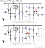
After sitting around for a while I am back to working on my Janus Shunt regulator and Aikio octal build. I was in the process of testing the heater side of the janus shunt regulator when diodes D2 and D5 gave up the ghost. I checked their orientation and they are orientated correctly. The configuration is setup as a fullwave bridge rectification with two tranformers one for the B+ and one for the heater. The B+ transformer is an Edcor XPWR163 which is a 120V, 60Hz. line to 550V (275-0-275) at 150mA center tapped, 6.3V (3.15-0-3.15) at 5A center tapped and 5V at 3A. I am not using the 6.3V tap. The heater transformer is a Hammond 167N12 which is a 12.6V CT transformer.
I measured the Hammond transformer and I am get just over 14V out of the secondaries.
The diodes are MUR410G which have a 4A rating, the secondaries on the Hammond have a 4A rating. Do I need to step up to a diode with a larger amp rating? I am trying to post a schematic but D2 and D5 make up have of the rectifier.
Attachments
Last edited:
- Home
- Amplifiers
- Tubes / Valves
- Janus Shunt Regulator / Aikido Octal build