You'll want to choose your power transformer to suit your intended circuit. You didn't say what the project is. What is the intended DC voltage, and how much steady state current will the circuit draw?
Also, how much current can that Janus regulator deliver? Will it deliver the current your circuit is likely to draw?
--
Also, how much current can that Janus regulator deliver? Will it deliver the current your circuit is likely to draw?
--
I apologize I thought I had that in the title of this thread, this is a preamp build.
Something like this then?
370BX Hammond Manufacturing | Mouser
Something like this then?
370BX Hammond Manufacturing | Mouser
Last edited:
By four 6SN7s do you mean four twin-triode tubes? If so,
- Each 6SN7 holds two triode sections, so that's 8 triode sections total.
- Each 6SN7 triode section will probably draw about 8mA.
- 8x 6SN7 triode sections drawing 8mA each means 64mA current draw.
Looking at Broskie's Aikido Octal PCB, it looks like four 6SN7s are used for stereo. Therefore, a 100mA rated power transformer should be plenty.
6SN7 tubes like fairly high plate voltages. I'm not sure what your target B+ voltage is. 300V? 400V? Other?
If 300V (what Broskie often uses), then you'll want about a 350V raw DC supply feeding the regulator.
Do you plan to use a tube rectifier, or solid state rectifiers for the raw supply?
If you use a solid state rectified DC supply feeding raw voltage to the Janus regulator, then a 550VCT at 90mA transformer should do. That's approximately 50VA. 100VA would be fine too, but way overkill.
If using a tube rectifier, then you have to factor in the voltage drop across that tube rectifier. Figure on about 25V dropped (ballpark guesstimate -- will vary depending on actual tube chosen). Therefore, you need a higher voltage transformer (but the same current rating). Figure if using a tube rectifier that you'll want a 600VCT @ 90mA transformer. That's about 54VA. Again, 100VA would work, just would be overkill.
Any questions, feel free to post 'em.
--
Last edited:
Do you plan to use a tube rectifier, or solid state rectifiers for the raw supply?
--
I plan on using a tube rectifier, more specifically a 5AR4/GZ34 because I have a few nice ones squirreled away for my Dynaco ST-70s.
Looking at the Janus product page (Janus Shunt Regulator Kit) I see that it's rated for power transformers from 400VCT to 550VCT
"Kit does not include a power transformer. Works with transformers between 400V to 550V center-tapped, with 5V @ 2A and 6.3V or 12.6V windings."
It's already designed to use a 5Y3GT rectifier tube. The 5AR4 will work too, but will drop less volts.
Each of the four 6SN7s' heaters draws 600mA. With four of them, you'll need a 3A rated heater winding. What I can't tell from the product description is exactly how the heater supply DC is derived. Does it use a voltage doubler on the 6.3VAC winding to get 12.6VDC, and then regulate down from there to 6.3VDC? If so, the current requirement also has to be doubled, so your 2.4A for the 6SN7 heaters has turned into a 5A requirement.
So your target is now 550VCT @ 90mA, 5.0V @ 2A, 6.3VCT @ 5A
--
Thank You! This has been a huge help.
I have been reading page 21.
http://glass-ware.com/User_Guides/Janus Rev A.pdf
I have been reading page 21.
http://glass-ware.com/User_Guides/Janus Rev A.pdf
The below is what has me confused. Broskie talks about using a separate transformer for the heater supply and I can see why if one chooses to go with a FW Bridge. If I choose to use one transformer and use the 6.3V @ 5A tap then I set the heater supply part of the PCB as a voltage doubler correct? Is their any benefits to having a separate transformer for the heater supply? I have read his reasoning and for an amp it makes sense but for a pre it appears to be over kill.
7-8Vac @ 5A for 6.3Vdc (FW Bridge)
12-12.6Vac @ 2.5A for 12.6Vdc (FW Bridge)
6.3-8Vac @ 5A for 12.6Vdc (Voltage Doubler)
7-8Vac @ 5A for 6.3Vdc (FW Bridge)
12-12.6Vac @ 2.5A for 12.6Vdc (FW Bridge)
6.3-8Vac @ 5A for 12.6Vdc (Voltage Doubler)
Last edited:
It's easiest to buy a separate small trafo for the heaters, that's what I did. Do a search on this forum on Aikido, and you can find info on what kind of trafo would work, or hopefully someone will chime in. I'm traveling now and don't have access to my files to find out at the moment.
PJN
PJN
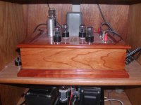
This is how I did mine. I ended up using two transformers just because I had the 12.6 VAC one. I also used the transformer 6K56VG Allied Electronics with a 270- CT -270. My initial design was for solid state rectification but the transformer was not suitable. Hence the heater switch hole.
A big shout out to Neville who sold me the board. I switched most of the components so I could get such a clean mount.
Not as quiet as my tube Schiit headphone preamp but it sounds really good! I mean really good.


A big shout out to Neville who sold me the board. I switched most of the components so I could get such a clean mount.
Not as quiet as my tube Schiit headphone preamp but it sounds really good! I mean really good.
There is a school of thought that says using a heater winding on the same core as the plate supply will inject some rectifier switching noise from the plate supply into the heater supply. If that is true, then using a separate transformer for the heater supply will remove that possibility. There are others who think that's all nonsense.
If you choose to use a heater winding that's on the same core as the plate supply winding, and that heater winding is 6.3V, you have to remember that full-wave rectifying 6.3VAC may not give you a high enough DC voltage to ensure that an LM317-type regulator doesn't drop out.
6.3VAC * 1.414 = 8.9VDC
minus the diode voltage drop of about 0.7VDC (to as much as 1.4V), so
8.9VDC - 0.7VDC = 8.2VDC (let's say 8VDC to account for winding resistance losses)
Now, we're regulating 8VDC down to 6VDC, which allows for a drop of only 2V through the LM317-type voltage regulator IC. However, an LM317 really should be allowed to drop at least 3VDC to keep it well clear of its dropout voltage. That's why you'll want to use a voltage doubler if you only have a 6.3VAC winding to work with. (The regulator IC can drop 6V, well clear of its dropout voltage.)
However, using a voltage doubler has the side effect of cutting the current capacity of the heater supply in half. Since you have to light up four 6SN7 heaters, which draw 0.6A each, you must have 2.4A current capacity from your heater supply.
Let's say you have a 6.3VCT heater winding rated at 4A. Using a voltage doubler on that will mean the resulting supply will only be good for 2A (half of the 4A rating without the doubler). You will need a 6.3VAC winding that's rated for 5A if you use it with a voltage doubler.
Also important -- an LM317 is good for only 1.5A. You should use an LM338 instead (5A capacity). It will need a good heatsink and thermal paste.
_______________________________________________
It looks like this (very inexpensive) Antek power transformer would work:
AS-1T275 - 100VA 275V Transformer - AnTek Products Corp
But it is out of stock.
There's an Edcor transformer that would work for less than $60:
https://edcorusa.com/xpwr163
550VCT @ 150mA, 6.3VCT @ 5A, 5.0VAC @ 3A
Bear in mind that it takes a month or so from when you place your order to when you actually get the transformer, since Edcor builds to order.
Hammond makes something too:
270FX Hammond Manufacturing | Mouser
550VCT @ 175mA, 6.3VAC @ 5A, 5VAC @ 3A
________________________________________________
You can find 12.6VCT @ 3A filament transformers surplus. They're very common.
Better yet, Antek sells a 9VAC 50VA toroid. 9VAC should give you about 11VDC after rectification. That leaves 5V dropped across the LM338.
http://www.antekinc.com/as-0509-50va-9v-transformer/
--
Last edited:
I've built several of the 6SN7/6SN7 Aikido linestages. I used what I had on hand for power transformers and thus was not able to roll any 12volt 12SN7's. If it were me and I was planning another Aikido I would simply add a double pole double throw switch and a suitable 12 volt heater transformer. I never had to supply the heaters with DC and my linestage is 100% quiet. I can appreciate wanting to use a 5Ar4 and to possibly roll the rectifier tubes. In my case I use 5Y3's, 5Ar4's, 5U4's, # 80 and number 83 for rectifiers. The number 80 and number 83 require a hand made adapter to go from a 4 pin base to a octal socket. My favorite tube is either the number 80 or the Mercury number 83. Good luck on your build.
Attachments
This might be a stupid question but what would be the "right" way of doing it, voltage doubler vs full-wave rectifying? If they both can get the job done is one preferred over the other?
Is there any differences between Edcor vs. Hammond? I like the price of the Edcor but not a fan of the wait time. I was hoping to get this done over the holidays but the price of the Edcors may win out.
I appreciate everyone's input so far especially rongons. I can not thank you enough for being patient with me and answering my questions. You explanations have been extremely well written and very helpful!
This might be a stupid question but what would be the "right" way of doing it, voltage doubler vs full-wave rectifying? If they both can get the job done is one preferred over the other?
Full-wave is preferable, but if you have to use a voltage doubler to get the job done, then that's what you gotta do, ya know? Just make sure to do it correctly. Capacitor voltages need to be high enough, and capacitance values need to be high enough (both should be double what you'd need for full wave rectification).
Places to read introductory material on voltage doubler circuits:
Voltage Multiplier and Voltage Doubler Circuit
http://www.vishay.com/docs/88842/anusingr.pdf
I'm glad to help.

--
Last edited:
en-process of getting mine finished up in its final home. Built it first on the boards and then wanted to move it to an enclosure so I'm working on that.
I ended up using a 12VCT trafo from radioshack for the heaters just because the power iron I had around didn't have heater windings. Mine was built using a 6n1 and 6n6 for the input and output stage respectively. just re-biased things a bit and it was great sounding. Can't wait to get this back together.
I won't be able to do a whole lot of rolling as I series/parallel wired the tubes to get both the 6n1 and 6n6 to feed off the same heater trafo.
Guts so far: http://i.imgur.com/IEyvsZU.jpg
the outside (top one): http://i.imgur.com/DTQjdjK.jpg
One additional thing you might want to look into is what cavalli did with his "improved" version and add some NFB.
https://www.cavalliaudio.com/diy/cj/main.php?page=cj
he's got a variable pot put in there but best of what I can tell that's going to be real similar in approach to what schiit uses with their hi/lo Z swtiches. Note, I've never had one apart and only own a Fula myself but this just comes from speculation with a fellow audiophile that owns a rather large stack of schiit.
In theory it works as you would think as well (cavalli touches on it a bit). Adding some NFB will bring the output impedance down as well as help with any noise. With my 55ohm cans I get a bit of noise floor in it that isn't apparent with say a 300ohm set of cans. So by adding the NFB with a hi/lo Z switch (or pot) you're going to kill 2 birds with the one stone; lower the output impedance if you need to and help with any noise.
I will probably go with the below combo then. I know they both don't have to be the same manufacture but their is a slight aesthetic part of this build that is also at play.
https://edcorusa.com/xpwr163
https://edcorusa.com/lvp12_6-3-120
https://edcorusa.com/xpwr163
https://edcorusa.com/lvp12_6-3-120
For educational purposes can one exceed amps? For example you need 12.6VCT @ 3A but can find/purchase or have a 12.6VCT @ 4A or higher transformer?
Any recommendations on a heatsink for the LM338? Is their a standard width for these? I am looking through mouser and there are a few width sizes to choose from.
Any recommendations on a heatsink for the LM338? Is their a standard width for these? I am looking through mouser and there are a few width sizes to choose from.
Last edited:
For educational purposes can one exceed amps? For example you need 12.6VCT @ 3A but can find/purchase or have a 12.6VCT @ 4A or higher transformer?
You can use a transformer with a higher current rating than you need, but you can't use a transformer with a lower current rating than you need.
Any recommendations on a heatsink for the LM338? Is their a standard width for these? I am looking through mouser and there are a few width sizes to choose from.
The LM338 is a TO-220 size package. Use a heatsink suitable for TO-220. Make sure to use mica spacers, thermal paste, etc.
Remember that if you have a 16VDC raw heater supply and you regulate down to 6V at 2.4A, your LM338 will be dropping 10V at 2.4A, or 24 watts (Hot!!). You will need a pretty capable heat sink.
Broskie makes a heater regulator board that he says is good for up to 2.5A current. You might want to go with this if you're buying Aikido and Janus boards from him already: H-PS-1 low-voltage regulator
You can also use a 5VAC filament transformer rated for 5A or more, and use a voltage doubler for a raw supply of about 10VDC. (Hammond 166R5 with paralleled primaries would work.) Then you can regulate down from there to 6VDC. You'll still need that heatsink, as the LM338 will be dissipating nearly 10 watts. Use a 10,000uF 25V capacitor before the regulator, to reduce ripple to manageable levels. John Broskie sells a little board for just this purpose -- New PS-9 Heater Power Supply
This is one of those topics that I'm sure is covered in many threads on this forum. A quick googling yielded these:
The Valve Wizard
https://www.cavalliaudio.com/diy/ehha/main.php?page=tweaks/heaters
--
- Home
- Amplifiers
- Tubes / Valves
- Janus Shunt Regulator / Aikido Octal build