My original PCB's were all done on paper and transfered by hand to the copper using transfers and ink... no PC and unfortunately no copies.
I might post details of a simple switch on delay and relay circuit on the main thread but I'll have to design it first")
I'll post a bit more later... short on time now
I might post details of a simple switch on delay and relay circuit on the main thread but I'll have to design it first
I'll post a bit more later... short on time now
Have a look at this,
http://www.diyaudio.com/forums/soli...al-speaker-delay-using-triac.html#post3269862
http://www.diyaudio.com/forums/soli...al-speaker-delay-using-triac.html#post3269862
Thank very much. I don't understand what is the reason or motive of using a triac instead of a transistor?
An increase in current through the relay coil very slow (due to the RC network) could cause the relay will not activate?
An abrupt change in the current of the relay is the main reason for using a triac?
Thank!!
An increase in current through the relay coil very slow (due to the RC network) could cause the relay will not activate?
An abrupt change in the current of the relay is the main reason for using a triac?
Thank!!
Thank very much. I don't understand what is the reason or motive of using a triac instead of a transistor?
An increase in current through the relay coil very slow (due to the RC network) could cause the relay will not activate?
An abrupt change in the current of the relay is the main reason for using a triac?
Thank!!
The triac allows the current to be switched on quickly in the relay coil. If we switch it on quickly we can use the trick of the "boost or kick" capacitor to really snap the contacts together with considerable force. The two benefits of that are that the contacts close with a definite action and also that having closed the relay current can be reduced to a "holding" value. That saves power and runs much cooler. For the capacitor trick to work, the switch on action has to be quick because there is limited energy available in the charged up cap. That's an important point.
To use a transistor we have the problem of the device coming "slowly" into conduction as the base current increases. That means the relay current increases relatively slowly and so the charge available in the boost capacitor is "wasted" and is non effective. To get the relay to work reliably like this would mean ensuring that the relay is fed with its rated coil voltage when the transistor is on. We couldn't use the same power saving technique because we couldn't get the contacts to "snap" closed like we can with the triac.
Two transistors could be used in a Schmidt trigger type arrangement but again there is additional complexity.
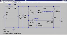
Here's a super simple version using a single FET. As the gate threshold voltage is passed the FET conducts. Use of a FET means we can use small currents in the timing network, in other words high value resistors and small caps.
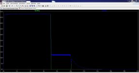
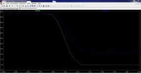
Look how slow the switch on is as the gate voltage increases. The same effect happens with an ordinary transistor except here we talk in terms of current rather than voltage.
This slow switch on means the 33uf cap dissipates its charge slowly and doesn't kick the relay closed. We have no power saving here, The 12 volt relay needs 12 volts.
That said its a very workable circuit for those that want the simplest approach.
Can you see why D3 had to be rearranged to discharge the timing cap on switch off ?
Edit... the zener is actually a 15 volt and not 6.3 as in the blue text on diagram.
Attachments
Last edited:
LT Spice simulation does not confirm this transistor being too slow behaviour....................To use a transistor we have the problem of the device coming "slowly" into conduction as the base current increases. That means the relay current increases relatively slowly and so the charge available in the boost capacitor is "wasted" and is non effective. To get the relay to work reliably like this would mean ensuring that the relay is fed with its rated coil voltage when the transistor is on. We couldn't use the same power saving technique because we couldn't get the contacts to "snap" closed like we can with the triac.
My ear "hearing" the relay click over also confirms a very snappy action using the resistor + capacitor triggering trick.
I have been recommending it for a long time.
Use 50% more voltage than the relay rating and insert a resistor of value between coil resistance (for 75% running voltage) to twice the coil resistance (for 50% of running voltage).
I have not experienced any slowness in the transistor switching action using this technique.
But the transistor must be saturated, i.e. the predriver transistor must deliver ~ Icoil/10 to the base of the switching transistor.
If a 12V relay has a 300ohm coil then 40mA is the rated coil current.
Using an 18V regulator as the circuit supply with a 300r resistor in the relay coil route then the predriver transistor must supply 4mA to the switching transistor and the final voltage across the relay is ~9Volts and the final current is ~30mA. Simulation generally shows that the "current pulse" from the overcharged capacitor is at least 3ms long and this exceeds the ~2ms closing time quoted for these relays, i.e. the cap enhanced current lasts longer than it takes for the relay to complete it's changeover action.
I'm sure driving a bjt transistor hard enough will get it to switch quickly enough. The triac circuit is extremely effective though.
Like you, I go a lot off how the actual circuit "feels and sounds" in use and to hear (and see) the relay contacts close very smartly is proof enough of the effectiveness of the design.
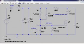
The Super Simple Circuit is actually missing a vital component which I've just spotted... the hazards of designing a circuit on the fly. The Vgs of the FET could be exceeded depending on supply voltage so a 15 volt zener added. The 6.2 zener now really is a 6.2 volt device. Sorry about that folks
Like you, I go a lot off how the actual circuit "feels and sounds" in use and to hear (and see) the relay contacts close very smartly is proof enough of the effectiveness of the design.
The Super Simple Circuit is actually missing a vital component which I've just spotted... the hazards of designing a circuit on the fly. The Vgs of the FET could be exceeded depending on supply voltage so a 15 volt zener added. The 6.2 zener now really is a 6.2 volt device. Sorry about that folks
Attachments
Hi Karl!!
I'm studying Douglas' book and i have one doubt, where is feedback loop? Could be R14,C3 and R7?
Please, could you tell me if i'm right?
Q1 => Singleton input stage, why is not used a differential pair?
Q4 and Q5=> VAS
Q2 and A3 => VAS current source.
Q6 and Q7 => Driver of Mosfets.
Thank you very much!!
PD: Bear: Thanks for your advices. I'm designing a new PCB. I use kicad as design software.
KiCad EDA Software Suite - Kicad EDA - KiCad EDA
Thats right, the feedback is via R14, R7 and C3.
Why not a differential stage Because that changes the whole behaviour of the amplifier and the spread of the harmonic distortion it produces. This single ended stage is one of the major reasons the amp sounds as good as it does.
Why not a differential stage
Because that changes the whole behaviour of the amplifier and the spread of the harmonic distortion it produces. This single ended stage is one of the major reasons the amp sounds as good as it does.The single ended stage produces 2nd harmonic distortion (which is pleasing to the ear). This distortion, although higher in absolute terms than that produced by a differential stage, also rises at a slower rate with frequency when compared to the differential stage.
Distortion isn't always bad (and we are talking very small levels anyway), and if you get that distortion "right" then you can have an amplifier that really sings.
Distortion isn't always bad (and we are talking very small levels anyway), and if you get that distortion "right" then you can have an amplifier that really sings.
Yes, and more than similar because it is class A.
Don't confuse class A small signal circuitry with Class A push pull output stages. All small signal low level audio stages normally run in class A. Both sides of the differential amplifier run in "class A" too.
The reason you get the even harmonics with a single transistor is because of the transistors non linear transfer characteristic. In the differential pair this distortion can be be "mirrored" or cancelled out. The better the balance of the differential amp and the lower the even harmonic distortion can become... which sonically is not necessarily always a good thing.
- Status
- This old topic is closed. If you want to reopen this topic, contact a moderator using the "Report Post" button.
- Home
- Amplifiers
- Solid State
- It helps to select best class power amplifier (AB- 40-50 watts)