sounds like a backwards output transformer connection.
but prove the circuit first by removing the feedback out of the circuit. troublshoot any noise, then the connect the feedback. if you get motorboating or other oscillations, the secondary of the output transformer is backwards.
but prove the circuit first by removing the feedback out of the circuit. troublshoot any noise, then the connect the feedback. if you get motorboating or other oscillations, the secondary of the output transformer is backwards.
sounds like a backwards output transformer connection.
but prove the circuit first by removing the feedback out of the circuit. troublshoot any noise, then the connect the feedback. if you get motorboating or other oscillations, the secondary of the output transformer is backwards.
Thanks, yea, that might be. But since a sinewave is in phase on input and output, both on what I now have as 8 ohm and 16 ohm tap, and as far as I understand it the signal inverts two times, I assumed that this must be right. But I might be wrong on that.
I was really surprised how much the feedback applied took the signal down though. I had to use at least two clicks on the scopes second channel voltage scale to get anything that wasnt a straight line when taking fb from the 16 ohm tap instead of with no fb.
Unfortunately I didnt write down any figures but assumed it was right and carried it out for a listening test after getting the phases to what I thought was right.
make proper LTP on input , with decent CCS in tail fed from neg PSU , then bring feedback to inside LTP half grid
with that cheapskate approach schematic , you are biting air all the time
ZM you might be right that I could choose another circuit. I was curious about the floating paraphrase though, and my plan was just to get the original stable and playing, then develop it further. First modernising would probably have been some diode bias on the 12AX7s, maybe a CSS or a regulator. Splitting up shared bias on output tubbies and listen for differences etc.
Unfortunatly I never got it stable on first build, but apart from that I like the basic sound very much.
It was stable with higher fb resistors with fb taken from what I then used as 8 ohms taps, so now my fool hardyness tells me that it would be possible to make it stable, if I just have everything in the OPTs in order, and apply the right amount of feedback from that.
Well I'll give it some more tries I think.
Done some reading up on thr OPT´s.
Black is secondary 0.
So you have to switch the primarys to get it in phase.
Now you are taking output between 8-16 ohm taps.
Challenging amp it even keeps me busy
Thanks, I'm very greatful. It has been spinning in my head today at work if it would make a difference 0-8-16 if plugging it backwards, if I also plug the primarys vice versa.
I will certainly try that later. About the boating I am a little suspicious about that the phasesplitters actually send some DC through secondarys. Thats why I was in to diodebiasing and skip the 100 uF.
But thats another story.
Ill stay in touch
1k is a a lot of negative feedback. 10K-47k might work for you better since the drive gain is high. there has been one time I set up an amp with nfb at 1K but in that instance took the fb signal through the 4 ohm connection and my input was a 12au7.
but I will stress to you use the NFB for gain control. not noise cancellation purposes (clean up the circuit first ).
but I will stress to you use the NFB for gain control. not noise cancellation purposes (clean up the circuit first ).
Ok. I'm on to something.
Well first I changed all the OPT Cables, anode and G2 on each tube per channel traded places and so did 0 (black) and 16 (cotton yellow/plastic yellow). Not a greater difference, still boating. But now its at it should be
So I started to rig a 1 kHz 1 Vpp sine, put it on on one channel, probe 1 on input tubes grids and probe 2 on output tubes grids, one after another.
You can see I have smaller unbalance but... last one started jumping (boating). So now I can concentrate my search to that. First change the coupling cap maybe.
Attachments
Coupling caps? How do I do that? Its kiddo evening so it might be sporadic work. Or tomorrow.
Yea I know. Thing is that I have redone PSU like 3 times. Not that that is any warranty, absolutly not but I would be a great builder if I could manage to get the same phenomenon from so many different PSUs. Is my little theory. For now
Yea I know. Thing is that I have redone PSU like 3 times. Not that that is any warranty, absolutly not but I would be a great builder if I could manage to get the same phenomenon from so many different PSUs. Is my little theory. For now
in series with µAmeter put the foil cap to dc supply (do not blow the meter first)Coupling caps? How do I do that? Its kiddo evening so it might be sporadic work. Or tomorrow.
Yea I know. Thing is that I have redone PSU like 3 times. Not that that is any warranty, absolutly not but I would be a great builder if I could manage to get the same phenomenon from so many different PSUs. Is my little theory. For now
in cap datasheet is written max leakage current, and measurement requirements
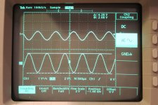
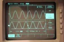
Well. Quick update. I made some proper measures on the setup without changing anything. When I measured the same EL84 grid again today there was no jumping on that one. Pic 1
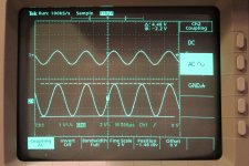
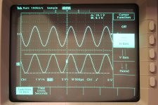
Measuring its opposite partner in crime gave about the same but inverted signal. You can see values delta cursors top right in window. Pic 2
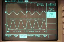
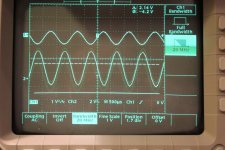
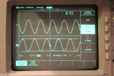
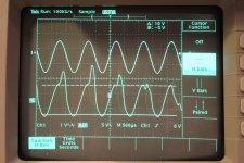
Next channel started ok on first grid, pic 3 but then I had another not yet seen strange wave on the last grid. Pic 4
Output is around 3 watts per channel with 2,14 Vpp input signal at 1 kHz with the 1 k fb resistor on 16 ohm taps. All the EL84 grids gets around 10 Vpp.
Then I measured a grid that hade a fine sine again and started changing input frequence on my signal generator. Then the that one started to pulsate. Thats clearly the motorboating, I recognised its behaviour. Pulsating around a Hz or a half maybe.
So I changed all the coupling caps to 0,18 mustard drops but that didnt change any behaviour.
My conclution is that there is something in my physical setup that I cannot find that haunt me and I give this up. It can be a bad joint, components that interfere, bad sockets anything.
Maybe I'll tear it out and rebuild or just start another build. We'll see.
Thanks for help anyway, I learned alot.
Staffan
Measuring its opposite partner in crime gave about the same but inverted signal. You can see values delta cursors top right in window. Pic 2
Next channel started ok on first grid, pic 3 but then I had another not yet seen strange wave on the last grid. Pic 4
Output is around 3 watts per channel with 2,14 Vpp input signal at 1 kHz with the 1 k fb resistor on 16 ohm taps. All the EL84 grids gets around 10 Vpp.
Then I measured a grid that hade a fine sine again and started changing input frequence on my signal generator. Then the that one started to pulsate. Thats clearly the motorboating, I recognised its behaviour. Pulsating around a Hz or a half maybe.
So I changed all the coupling caps to 0,18 mustard drops but that didnt change any behaviour.
My conclution is that there is something in my physical setup that I cannot find that haunt me and I give this up. It can be a bad joint, components that interfere, bad sockets anything.
Maybe I'll tear it out and rebuild or just start another build. We'll see.
Thanks for help anyway, I learned alot.
Staffan
Attachments
Last edited:
Never let a piece of equipment beat you
If it still does, do as the politicians.....denie !!
The project is now in a phase of longterm evaluation......
Hehe. Your right. First thought is Always to look around for another hobby. After a coffee it gets like: Well I'll leave that bl..dy circuit anyway.
Then after cleaning the desk and getting some air. Well the present build anyway
Sorry to see the project come to an end, Stajo. Troubleshooting can be a frustrating experience, but thanks for sharing your efforts with all of us.
We all learn from such efforts - and wish we could be looking over your shoulder or playing with the probze, it's always an interesting puzzle.
Wish we knew what the real problem was, and that we could put the lesson into our little black books of "Do NOT do THAT in the future" knowledge!
If everything went right all the time then we wouldn't be pushing our limits and learning new things to avoid!
One final question (from me, at least) - can you tell us whether the 50uF "Motor Capacitor" on the output of the 6AX4 pair (ahead of the 150 ohm resistor in your power supply sketch in Post 58) is a "Start" or a "Run" capacitor? For some reason, it looks to me like it might be a "start" type but they come in all shapes and sizes and I'm certainly no expert at identifying them by shape.
And I will share with you that from my viewpoint your last scope-photo (#4) appears to have some mains-frequency in it causing the "jiggles" on the 1kHz sine wave. At least, the period of the jiggles appears to work out to be around 50-60Hz which immediately makes me think "Mains Frequency" for some reason.
It is a reach, especially since I'm not viewing the waveform real-time, but I'll bet the distortion is "walking" through your 1kHz tone - if the jiggles are NOT walking through the 1kHz wave, then the two waveforms are synchronous (locked) together which means it's probably coming from your generator.
Best luck with whatever you decide to do with the parts - you at least have the makings of a new project!
Best Luck whatever you decide to do!
Sam
We all learn from such efforts - and wish we could be looking over your shoulder or playing with the probze, it's always an interesting puzzle.
Wish we knew what the real problem was, and that we could put the lesson into our little black books of "Do NOT do THAT in the future" knowledge!
If everything went right all the time then we wouldn't be pushing our limits and learning new things to avoid!
One final question (from me, at least) - can you tell us whether the 50uF "Motor Capacitor" on the output of the 6AX4 pair (ahead of the 150 ohm resistor in your power supply sketch in Post 58) is a "Start" or a "Run" capacitor? For some reason, it looks to me like it might be a "start" type but they come in all shapes and sizes and I'm certainly no expert at identifying them by shape.
And I will share with you that from my viewpoint your last scope-photo (#4) appears to have some mains-frequency in it causing the "jiggles" on the 1kHz sine wave. At least, the period of the jiggles appears to work out to be around 50-60Hz which immediately makes me think "Mains Frequency" for some reason
. It is a reach, especially since I'm not viewing the waveform real-time, but I'll bet the distortion is "walking" through your 1kHz tone - if the jiggles are NOT walking through the 1kHz wave, then the two waveforms are synchronous (locked) together which means it's probably coming from your generator.
Best luck with whatever you decide to do with the parts - you at least have the makings of a new project!
Best Luck whatever you decide to do!
Sam
Hello Sam, and thanks again for your help and efforts!
To be honest I dont really trust myself when postulating that this project is over. Firstly I have just started to scetch up a physical layout for a PPP version of something in like this. Secondly, I'm sure after some cuts and bruisers fixing/changing power transformer, maybe desoldering and examining the rest of the componens I put it together again. Those who live will be able to tell...
About the PSU, caps etc I'm afraid that I missed some parts when a bit to quickly drawing up the schema. For the EL84 output department all is correct though. I have the pair of 6AX4 as forward diodes in a graetz followed by a 50 uF motorrun which is an Epcos MKP 450 VAC. Its many numbers on it but I think B32328 might be a Product number.
6AX4 katodes goes directly into that one and with another wire to the 150R powerresistor. The motorcap returns directly to PSU starground together with return diodes and the four 47 uF lytics.
In the PSU for the 12AX7s I forgot one step which is after 15H choke, theres a 47 uF PEG124 which splits in two 6k8 resistors and finally the two 47 uF PEGs. So a C-L-C-doubleR-doubleC or something
Regarding the visible symptoms I had 3 different. First was a "dancing" sine (last one post #88) on one EL84 grid. Next day that grid was fine, but one on the other channel made other behaviours (post #92). All others nice. Then I could also provoke the actual motorboating, which I dont have a picture on but I'm sure it would have appeared on all 4 grids. Its a slower "dance" then in post #88. Like a distant fishingboat in the horizon moving the sine up and down when the "AC setting" on the scope cant center it
That one I can provoke to come by pushing frequency buttons in a fast serie on my generator. I think I said before that the amp is stable at Power on. It takes a signal in to start. But if I then cut the signal, the boating remains.
Along with the "sporadic" malfunctions and the fact that the build is some years old, I thought its more efficiant to start all over then trying to reverse engineer it.
Thanks for sharing your knowledge and comments and please continue with that. Here or in other threads.
Thanks
Staffan
Forgot. About the wiggles on the sine in last pic post #92 I was in to that the feedback for some reasons dont work, gets disturbed or something. You can see that the amplitude "strikes through" and gets higher. Just like on startup when the EL84rs not have biased up yet and thers no feedback, then the amplitude is way higher.
Why they get higher in just the "tops", and not the "valleys deeper". I have no idea.
But what do I know..
Staffan
Why they get higher in just the "tops", and not the "valleys deeper". I have no idea.
But what do I know..
Staffan
Last edited:
I was curious about the jiggle on the EL84 screen signal so I actually set it up during breakfast this morning and when starting the amp with the first probe on 12AX7 input grid (above gridstopper) and second probe after the coupling cap its all normal. If I move the second probe (I was trying to move it to the other EL84) the jiggle starts. Then I dont seem to be able to get it away.
For me this indicates a bad soldering or socket.
For me this indicates a bad soldering or socket.
- Status
- This old topic is closed. If you want to reopen this topic, contact a moderator using the "Report Post" button.
- Home
- Amplifiers
- Tubes / Valves
- ISO a motorboat