Fault hunting mode is on  .
.
Which OPT´s are we dealing with here exactly ?
Is it genuin or aftermarket ?
Looks like a genuine US made with the cloth wires.
Why i´m asking is because the aftermarket has 0-4-8 ohm taps instead of 0-8-16 taps.
An aftermarket with speakers at wrong tap gives issues.
Next step if the OPT is the right stuff disconnect FB loop and attach 1K to ground.
Now it´s grounding clean up time !
Are the different building blocks within the amp hooked togetter as in the schematic and then to starground ?
No groundings between channels and different stages before connecting to starground ?
Then PSU busbar grounding dirty end to rectifier clean to amp.
Time for listening test !
Is it behaving ?
.Which OPT´s are we dealing with here exactly ?
Is it genuin or aftermarket ?
Looks like a genuine US made with the cloth wires.
Why i´m asking is because the aftermarket has 0-4-8 ohm taps instead of 0-8-16 taps.
An aftermarket with speakers at wrong tap gives issues.
Next step if the OPT is the right stuff disconnect FB loop and attach 1K to ground.
Now it´s grounding clean up time !
Are the different building blocks within the amp hooked togetter as in the schematic and then to starground ?
No groundings between channels and different stages before connecting to starground ?
Then PSU busbar grounding dirty end to rectifier clean to amp.
Time for listening test !
Is it behaving ?
Thanks man. I had this accident yesterday, my son was close to it with some careless drivers. My nerves was inside out. Sorry, couldnt even hold the probe.
The OPTs are from some SCA-35s i guess, found them in Blommans boat
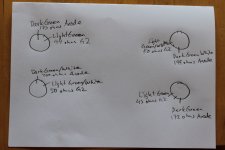
They have cotton on the primarys and if you have a very bright lamp you can differ between following colours. Dark green (200 ohmish)/lighter green (40 ohmish) seems to be one pair. Zigzag Dark green(200 ohmish) and lighter green/white zigzag (40 ohmis) seems to be the other pair.
Secondaries are worse. The common colour are black cotton, that I have as plus on both, I think 8 ohm tap. Then they have one yellowish (but different in nuance between the two) cotton to. I have that on gnd on both for now. Seemed to be when mounting.
This setup seemed right when mounting them but that was long ago and its been playing nice, exept for when the boating started. Other then that one has an orange plastic and the other is yellow plastic. Those I took as 16 ohmers when mounting them and have had them loose since now.
Ground: All audiogrounds stars in one leadstand. Its the one between RCAs and the Circuit. From there a 2 mm copper goes to a stand where all filtercaps grounds connect, plus the graetz return. The exeption is the ECC83s last 47 u:s that returns to audioground (mixed star/follow signal concept).
I will stopp silly myself today and do some proper maesurs. Its a bit tight around the splittertubbies and ofc I have soldered the secondaries so hard I practically burn the house when freeing them from speakerconnections.
Thanks for baering.
Staffan
The OPTs are from some SCA-35s i guess, found them in Blommans boat
They have cotton on the primarys and if you have a very bright lamp you can differ between following colours. Dark green (200 ohmish)/lighter green (40 ohmish) seems to be one pair. Zigzag Dark green(200 ohmish) and lighter green/white zigzag (40 ohmis) seems to be the other pair.
Secondaries are worse. The common colour are black cotton, that I have as plus on both, I think 8 ohm tap. Then they have one yellowish (but different in nuance between the two) cotton to. I have that on gnd on both for now. Seemed to be when mounting.
This setup seemed right when mounting them but that was long ago and its been playing nice, exept for when the boating started. Other then that one has an orange plastic and the other is yellow plastic. Those I took as 16 ohmers when mounting them and have had them loose since now.
Ground: All audiogrounds stars in one leadstand. Its the one between RCAs and the Circuit. From there a 2 mm copper goes to a stand where all filtercaps grounds connect, plus the graetz return. The exeption is the ECC83s last 47 u:s that returns to audioground (mixed star/follow signal concept).
I will stopp silly myself today and do some proper maesurs. Its a bit tight around the splittertubbies and ofc I have soldered the secondaries so hard I practically burn the house when freeing them from speakerconnections.
Thanks for baering.
Staffan
Other then that I gave it some time a year ago or so when I took it as a grounding problem. I tested various concepts on grounding but it didnt seem to differ. I left it by having the input tubbies with a single 6X5 and the output tubbies have dual 6AX4GTBs (dual diodes). Before that all shared a C-R-C with a GZ34. It made no greater differance, but it was a trial on separating the splitter tubes from the output tubes regarding feeding (RLD inspiration).
Enjoy !!
I´m on cleanup duty
Some tubes in the kitchen was acceptable.....cutting torch nozzles and heavy tooling wasn´t
Thats hard man. I have my MIG welder in the kitchen. I wonder why noone marries me
Stajo,
Have you tried what Mr Murre has said..ie disconnect the feedback and put a 1K to ground in place of it so you can see if the amp is stable without feedback..OK the sound will be louder..but is the amp stable with this done..
I guess you already know that the the first tube cathode circuit uses the feedback and Tx secondary for its circuit to Gnd...
So if you disconnect the feedback and put a 1K in place of it to Gnd the circuit will work without feedback...is the amp stable then?
Regards
M. Gregg
Thats hard man. I have my MIG welder in the kitchen. I wonder why noone marries me
You´re my everyday hero
.Now get that amp working or i will come on a dark night and install chipamps in all your equipment
 .
.Stajo,
Have you tried what Mr Murre has said..ie disconnect the feedback and put a 1K to ground in place of it so you can see if the amp is stable without feedback..OK the sound will be louder..but is the amp stable with this done..
I guess you already know that the the first tube cathode circuit uses the feedback and Tx secondary for its circuit to Gnd...
So if you disconnect the feedback and put a 1K in place of it to Gnd the circuit will work without feedback...is the amp stable then?
Regards
M. Gregg
Thanks M Gregg. Sorry again fore loosing my temper. I have started to maesure things. Before disconnecting GNF attatched is my config regarding OPT primarys and output tubbies.
I will now disconnect GNF and put 1 k to ground.
Attachments
You´re my everyday hero
Now get that amp working or i will come on a dark night and install chipamps in all your equipment
LMAO..he will you know honest...and they will be radio active (glow in the dark)...
Regards
M. Gregg
Thanks M Gregg. Sorry again fore loosing my temper. I have started to maesure things. Before disconnecting GNF attatched is my config regarding OPT primarys and output tubbies.
I will now disconnect GNF and put 1 k to ground.
Stajo,
If you are not sure about the OP winding..
Test to see which connections give the highest resistance readings..this "Should" be each end of the secondary (OP to speaker)...then you can see what colours you have as the start and end of the winding...
Back laters...
..let us know how you get on.Regards
M. Gregg
Last edited:
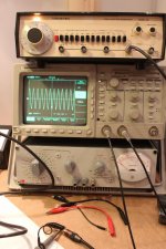
Ok, think my sanity is coming back slowly. Heres a signal from that to the scope. Is it a starter or should I change some params?
The 1 k is now back in line and the returns from that now goes to gnd instead of from the OPTs.
The 1 k is now back in line and the returns from that now goes to gnd instead of from the OPTs.
Attachments
Stajo,
Is the amp stable now?
The next question what about the hum?
This could be heater problems...how have you (Hum Bucked)<<ie do you have two resistors one from each side of the heater supply joined togeather and then to Gnd?
If you can get the amp working OK then you can tweek it..
Regards
M. Gregg
Is the amp stable now?
The next question what about the hum?
This could be heater problems...how have you (Hum Bucked)<<ie do you have two resistors one from each side of the heater supply joined togeather and then to Gnd?
If you can get the amp working OK then you can tweek it..
Regards
M. Gregg
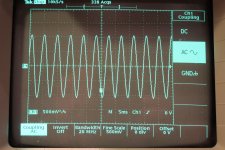
You guys enjoy movies? Heres Wavetek on 100 Hz 2 VPP and the grid on Tex. If I turn on the amp it makes strange noices. I hear the signal w/o speakers
hafler 005 - YouTube
Staffan
hafler 005 - YouTube
Staffan
You guys enjoy movies? Heres Wavetek on 100 Hz 2 VPP and the grid on Tex. If I turn on the amp it makes strange noices. I hear the signal w/o speakers
hafler 005 - YouTube
Staffan
Stajo,
Don't run the amp without speakers you will damage the OP Tx or have a dummy load resistor in place of them
Regards
M. Gregg
Are your heaters grounded with the CT of the 6.3v winding as shown in the circuit?
Is the Hum from the speakers or from the amp?
Regards
M. Gregg
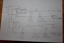
Heaters by two 100 ohm resistors to gnd I beleave atm. Heres http://www.youtube.com/watch?v=22TqAsDRYZQ&feature=youtu.be with some dummy speakers and a PSU scetch reengineerd by yours truly. I Think it matches and hope it makes sence.
Allah achbar
Attachments
A lot of parts makes excellent transducers just hook up a foil cap to an amp if you on´t believe it.
A couple of load resistors is a must when testing.
Or the powermeter set to 8ohm load.
Running an amp unloaded on idle is not recomemded.... but full tilt can cause voltage buildup and arcover in the OPT and then it´s end of story.
Check for phase between input/output.
A couple of load resistors is a must when testing.
Or the powermeter set to 8ohm load.
Running an amp unloaded on idle is not recomemded.... but full tilt can cause voltage buildup and arcover in the OPT and then it´s end of story.
Check for phase between input/output.
- Status
- This old topic is closed. If you want to reopen this topic, contact a moderator using the "Report Post" button.
- Home
- Amplifiers
- Tubes / Valves
- ISO a motorboat