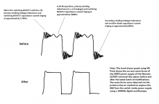
In the original Marantz player, the 9MHz OP275 has heavy compensation, with a 1nF in parallel with 820R, which has a -3dB corner frequency at 200kHz.
If I change it to the 100MHz LM6172, I think I will reduce the 1nF to 470pF to reduce the phase shift at 20kHz. In that case, the corner frequency will be shifted to close to 400kHz instead. When it reaches 10MHz, the attenuation is 30dB already, and I think that is a plenty.
Play around with the value of that cap and listen to how it affects the sound. In my understanding the cap is required to prevent the amp entering slew limiting, a highly non-linear condition. I found with the 6172 that the smaller that cap, the better the sound - in particular the clarity of the soundstage. I ended up with 4.7pF.
Thanks for your note.
There are currently 3 bypass caps on the positive rails: 470uF LOW ESL electrolytic, 0.1uF MKP + 0.5R, and the SMD 0.01uF right at the supply pin.
There are 2 bypass caps on the negative rails: 470uF LOW ESL electrolytic and 0.1uF MKP + 0.5R.
I have not soldered tiny SMD parts before so I would hesitate changing the 0.01uF cap.
I am thinking about replacing the 0.1uF MKP + 0.5R with 0.01uF through hole X7R (or 0.022uF NPO I have already had on my part bins). I prefer risking with some impedance peaking below the SRF of the cap than risking having much higher impedance above the SRF of the cap. This satisfies the demand in the datasheet. Although this is through hole instead of SMD, the extra length is merely the PCB thickness for the positive rail, but a 1.5cm track for the negative rail, which can ruin the thing.
If I could scrape a bit of copper near the negative supply pin I might be able to install a SMD low pF cap there and replace the 0.01uF SMD with a low pF cap like what you did.
The positive input of the LM6172 is grounded. Does this affect (i.e. ease) the rail bypassing? Has this anything to do with Marantz choice of bypassing +supply at the supply pin but not the -supply? I can't relate the inputs to the supply rails though.
OK, I finally got all the parts yesterday after 3.5 week wait for one part from the U.S. Now I finished the SMPS mod. This last batch of mod put on 17 new passive components onto the existing SMPS circuit, with 5 new components soldered on top of the board and the other 12 beneath the board.
Attached is the result.
Two months ago, when I got the schematic of the SMPS power supply I thought “what the hell was this…”, as I had never seen a SMPS power supply schematic. Now I have got the switching noise of a flyback SMPS down to the minimum, better than all text book examples / datasheets I have seen, while previously the noise was worse than all text book examples I have seen.
The damping of the 3.5MHz ringing can still be a bit better, and that is merely to increase the snubber cap from 100pF to 150pF up to 220pF without taking out the SMPS board. It will be a 1 minute job for me. For that particular snubber, I calculated the capacitor value to be about 500pF for a Q=0.5. However, this is the snubber across the switching MOSFET which means it has voltage swing in excess of 500V. I would much prefer to start from a small capacitance value as not to risk burning the resistor, therefore the initial 100pF was chosen. I am using 6W rated resistance (2 x 3W metal oxide resistors) there. I am confident that by increasing this capacitor value it will completely smooth out the ringing.
Even though all the ringings have now been removed or substantially reduced, I still don’t like the idea of SMPS in audio, especially in line level equipment. Last night I also did some brief direct measurements on the voltages for +/-12V at the outputs of the rectifier diodes. I still saw ripples with over 1V magnitude at the switching frequency of 100kHz. They used to ring for at least half a dozen cycles before dying down, and now it is only one and a half wave. Even so, I imagine with the very quick rise and fall time at 100kHz intervals at the magnitude of 1V the proceeding regulator stages will still have a very hard time removing the ripples completely. I could not measure this because there are no test points on the analogue board for me to do so.
But now with the 580kHz, 3.5MHz and 8MHz ringings all disappeared I suspect that the whole circuit ground is much cleaner than it used to be, with much reduced EMI radiation as well.
No, I don’t want to give you my subjective evaluation of the sound improvement to stir up your fancy. The drawing of the measurements shows what have been accomplished. The only thing I would like to say is that I listened to music from 7pm until midnight last night and did not want to stop, and the last piece I listened to was Pentatone SACD - Suburt Piano trio – not perfect, but fabulous now.
I would like to thank you people who have participated in this thread. Thank you for your advice, your encouragement, your interest and your participation.

Attached is the result.
Two months ago, when I got the schematic of the SMPS power supply I thought “what the hell was this…”, as I had never seen a SMPS power supply schematic. Now I have got the switching noise of a flyback SMPS down to the minimum, better than all text book examples / datasheets I have seen, while previously the noise was worse than all text book examples I have seen.
The damping of the 3.5MHz ringing can still be a bit better, and that is merely to increase the snubber cap from 100pF to 150pF up to 220pF without taking out the SMPS board. It will be a 1 minute job for me. For that particular snubber, I calculated the capacitor value to be about 500pF for a Q=0.5. However, this is the snubber across the switching MOSFET which means it has voltage swing in excess of 500V. I would much prefer to start from a small capacitance value as not to risk burning the resistor, therefore the initial 100pF was chosen. I am using 6W rated resistance (2 x 3W metal oxide resistors) there. I am confident that by increasing this capacitor value it will completely smooth out the ringing.
Even though all the ringings have now been removed or substantially reduced, I still don’t like the idea of SMPS in audio, especially in line level equipment.
Last night I also did some brief direct measurements on the voltages for +/-12V at the outputs of the rectifier diodes. I still saw ripples with over 1V magnitude at the switching frequency of 100kHz. They used to ring for at least half a dozen cycles before dying down, and now it is only one and a half wave. Even so, I imagine with the very quick rise and fall time at 100kHz intervals at the magnitude of 1V the proceeding regulator stages will still have a very hard time removing the ripples completely. I could not measure this because there are no test points on the analogue board for me to do so.But now with the 580kHz, 3.5MHz and 8MHz ringings all disappeared I suspect that the whole circuit ground is much cleaner than it used to be, with much reduced EMI radiation as well.
No, I don’t want to give you my subjective evaluation of the sound improvement to stir up your fancy. The drawing of the measurements shows what have been accomplished. The only thing I would like to say is that I listened to music from 7pm until midnight last night and did not want to stop, and the last piece I listened to was Pentatone SACD - Suburt Piano trio – not perfect, but fabulous now.
I would like to thank you people who have participated in this thread. Thank you for your advice, your encouragement, your interest and your participation.
Attachments
So what are next?
I still want to replace the dual 8-SOIC opamps from OP275 for I/V to LM6172, and NJM4565 (8-DMP) to LM4562. I know exactly what to change for the surrounding parts. I have already got the new opamps on hand.
I have not done SMD chip de-soldering and soldering before so I am quite nervous about it, even though I have seen a number of youtube videos for it.
I suppose the last items I would do to this player is to improve on the two very cheap SOT-223 regulators for the DAC, naming the 5v and 3v regulators, and their cheap output electrolytic caps which can get dried out one day. I have no ideas how to improve them. They are very cheap Korean made parts with different pin layouts from any common brands I have seen, which means I can’t find the parts I like to replace them. So I am pretty much stuck. They are marked as LDO regulators. I would not dare to change the onboard 100uF/16V capacitors after those two regulators into better quality low ESL type, because without knowing the behaviour of the regulators (datasheets have minimal information), I can make the circuit ringing like hell with low ESL caps. Most LDO regulators are very fuzzy with their output caps. I am REALLY stuck.
Any ideas from you?
Excellent result on the SMPSU, WTG
3 pin regs have very poor HF line rejection so how about putting filters on the input side of them first to see what happens sound-wise? Measure how much headroom they have first then choose an RC (or even LC) network accordingly.
Good thought.
But if I step back even one more step, I would ask "where is the noise coming from?"
(1) I can see the SMPS makes some pulses at the frequency of 100kHz, with much faster rise and fall time than 100kHz sine waves;
(2) Because of the multiple ground paths of the Marantz design, the ground noise from the SMPS as well as other boards will add to the noise source;
(3) The load of the analogue circuit after the DAC will generate noise; and
(4) The load of the digital circuits part of the DAC will generate noise - This is the part the 5v and 3v regulators are supply, our subject matter.
Now those are the main noise sources I can think of at the moment. I can't think of anything else that are significant.
With noise source (1), the SMPS noise is unlikely to be reduced. I have basically got the SMPS noise down to as good as it can get. Although there are no ringings any more, the current pulses on the rails when the MOSFET changes the switches will generate sharp voltage spikes, which are still as hard to filter as the previous ringing frequencies of 3.5MHz and 8MHz, for which I previoiusly tried LCR filters which failed to do much. Let us discuss more of this in the next post.
Noise source (2) is the most difficult to deal with because measuring the ground noise may be the hardest. My knowledge and experience on this is not much neither. It is impossible to change the SMPS board not to have the star ground on the output socket. It is impossible to change the PCB ground to chassis connection on the analogue/DAC board. I have not seen the main controller board but I guess it is probably grounded to the chassis too (i.e. two ground paths, like the DAC board). Isolating any of the board to chassis connection may increase the noise for the local boards. So basically I don't think I can do anything on noise source (2). Would any experts in this area head up and give some advice?
I don't think I can do much to noise source (3) neither, because the only way to reduce it is to improve on the +/-12V regulators, which are currently using cheap, fake, emmulated 7805 type of regulators. I have upgraded the local decoupling caps to 470uF/16V Rubycon ZL, which have a fairly low ESL/ESR that should work very well. Their ESL/ESR are not extremely low to give the regulators troubles. I selected the values based on assuming the regulators being LDOs such that the cap values and ESL/ESR won't alter the control loops of the regulators in a way to cause oscillation. I need to measure this one day to confirm my belief though.
Noise source (4) is my current problem.
I previously tried filtering the SMPS noise using LCR filters directly on the SMPS board and they failed to reduce the noise by much.
The reason was probably due to (A) the layout of the Marantz board is terrible and it caused problems like what I initially simulated, which prompted me to create this thread in the first place; (B) parasitic capacitance on the inductors; and (C) the impotency of the electrolytic capacitors beyond a few hundred kHz since we want to filter out 3.5MHz and 8MHz noise.
I then used ferrite beads that have some but limited success.
Now can I redo the LCRs again? Would out of the board LCRs work better since the ground noise won't influence the result anymore? Would it work by using ceramic NPO this time? Would the high Q ceramic caps cause new impedance peaks in the power supply that make noise worse?
HI, HiFiNutNut;3645529]
I am going to build the snubber test circuit soon and give it a go,lol.
I share your pain with smt devices ,I put my board vertical and swipe the legs with a butane torch and have a small screw driver to flick it off with ,when it 's ready to come off ,it will start slipping down the board,get a old MB or something with smt chips and practice,
Clean with the traces with solder wick or similar ,put some flux on the board pads and the chip on the board and solder it back,(i use a big fat sewing needle in a low watt soldering iron)You can put a little solder on the first pad to stick the chip in place,after you have it all soldered if you think it needs it ,re flow with the torch,
I use kester #951 liquid flux(dickiegaragesale.com) no clean up needed,when soldering the chip back on, do one leg and then the one on the other corner and get it straight on the pads, then solder the rest of the legs,I use a jewelers magnifier,and a good light!
I have had good results doing it this way so good luck to you too!
NS
lol.I have lost a few traces with a hot air blower but I have had good luck with the torch,
I have super glued a toothpick to the chip too and heat it and pull it off that way too,BTW some folks from germany glue the chips on that's the red dot you see on the board,but just give it a little pull and they come of intact,Have fun,lol.
NS
I have super glued a toothpick to the chip too and heat it and pull it off that way too,BTW some folks from germany glue the chips on that's the red dot you see on the board,but just give it a little pull and they come of intact,Have fun,lol.
NS
Play around with the value of that cap and listen to how it affects the sound. In my understanding the cap is required to prevent the amp entering slew limiting, a highly non-linear condition. I found with the 6172 that the smaller that cap, the better the sound - in particular the clarity of the soundstage. I ended up with 4.7pF.
Abraxalito,
I am about to start my 4th (final) round of mod to this player.
With the above quotation, I presume we are at the same pace talking about the I/V opamp which has the positive input grounded, and the negative input has a resistor connected to the output of the opamp.
You said that you found 4.7pF in shunt of the resistor sounded the best. Was your resistor value 820R? If not, I must adjust the cap value accordingly.
I have just used LTSpice to simulate the filter stage after the I/V opamp. Marantz' circuit has a response bump of 2.7dB at 45kHz! No wonder I found the top end of the Marantz player to be exaggerated. The DAC chip pcm1795's datasheet shows an example of 4th order filter with a corner frequency of 55kHz. I think that may be too conservative. Marantz put it in about 85kHz. I am thinking about moving it to 120kHz so that it can have less phase shift at 20kHz (15 degree instead of 36 degree phase shift). Even with a higher corner frequency, the LP filter will still have -116dB at 10MHz. That is really a plenty of roll-off for the LM6172. What do you think?
Also, I am thinking about having 0.01nF up to 0.1uF NPO or X7R directly on the opamp supply pins to ground for both the LM6172 and LM4562. I understand that they will create some impedance peaks in the low MHz region but I don't have a better way to bypass them. Padding with resistance may substantially reduce the effectiveness of the bypass. I think these high bandwidth opamps do really need them. What do you think?
Thanks and Regards,
Bill
Last edited:
I am about to start my 4th (final) round of mod to this player.
Final round, final eh?
With the above quotation, I presume we are at the same pace talking about the I/V opamp which has the positive input grounded, and the negative input has a resistor connected to the output of the opamp.
Yes - a transimpedance amp configuration.
You said that you found 4.7pF in shunt of the resistor sounded the best. Was your resistor value 820R? If not, I must adjust the cap value accordingly.
I don't have a precise memory, but it was around that value yes. My DAC was AD1955 though. I should point out that 4.7pF was the lowest cap value I tried as my cap supply was rather limited in those days - I actually used 2 * 10pF in series I think as 10pF was the lowest I had. I also tried with no cap at all as a comparison. Its possible that something lower than 5pF is optimum.
I have just used LTSpice to simulate the filter stage after the I/V opamp. Marantz' circuit has a response bump of 2.7dB at 45kHz! No wonder I found the top end of the Marantz player to be exaggerated.
What did that translate to in the audio band (for us oldies, say 15kHz) ? Not a lot I'd wager - probably not the cause of exaggerated top.
The DAC chip pcm1795's datasheet shows an example of 4th order filter with a corner frequency of 55kHz. I think that may be too conservative. Marantz put it in about 85kHz. I am thinking about moving it to 120kHz so that it can have less phase shift at 20kHz (15 degree instead of 36 degree phase shift).
I don't worry about phase shift nowadays as my passive filters have lots and lots. I do though get concerned about band-limiting, and a lower bandwidth tends to sound better (within reason of course!). I suggest not depending on the feedback cap for band-limiting, its primary purpose isn't that, rather prevention of slew-limiting.
Also, I am thinking about having 0.01nF up to 0.1uF NPO or X7R directly on the opamp supply pins to ground for both the LM6172 and LM4562. I understand that they will create some impedance peaks in the low MHz region but I don't have a better way to bypass them.
I reckon only do this if you maintain scrupulous hygiene between signal and power grounds. If not, it'll contribute harshness coz you'll couple PSU hash into the pin3 & 5 (+ve ins) of the LM6172 which are grounded.
Padding with resistance may substantially reduce the effectiveness of the bypass. I think these high bandwidth opamps do really need them. What do you think?
High B/W opamps certainly do need generous decoupling, but between pin4 and pin8 in the first instance. Decoupling to ground depends on what their output stage sees - where does the output current go and how does it return? Note that there's also the feedback current (via the 820R) and that'll return via the DAC.
I don't worry about phase shift nowadays as my passive filters have lots and lots. I do though get concerned about band-limiting, and a lower bandwidth tends to sound better (within reason of course!). I suggest not depending on the feedback cap for band-limiting, its primary purpose isn't that, rather prevention of slew-limiting.
For the filter stage (LM4562), the compensation / feedback cap is part of the 4th order LP filter. The cap does not need to be that large (2n2) for compensation, but is necessary for LP filtering, it is one of the caps that controls the bandwidth.
So you found bandwidth limiting is good. I used to install a trimpot for the input RC on my preamp. I determine the RC values by listening to the music. Indeed, there is an optimal point, above which the sound becomes a bit chilled, below which the sound becomes a bit dull.
But I can't imgaine here that a corner frequency of 120kHz to be too high. Since this is a 4th order LP filter, At 1MHz it is already 50dB down, and at 10MHz 116dB down. The LM4562 is a 55MHz opamp. I see no reason to lower the corner frequency futher. Bear in mind that this is for the CD player. There is at least another RC at the input of the preamp, and another one at the input of the power amp. Combined, it can even roll-off the frequency response at 20kHz.
I reckon only do this if you maintain scrupulous hygiene between signal and power grounds. If not, it'll contribute harshness coz you'll couple PSU hash into the pin3 & 5 (+ve ins) of the LM6172 which are grounded.
High B/W opamps certainly do need generous decoupling, but between pin4 and pin8 in the first instance. Decoupling to ground depends on what their output stage sees - where does the output current go and how does it return? Note that there's also the feedback current (via the 820R) and that'll return via the DAC.
This is a cheap machine. Marantz has already done that all over the places. It uses almost the entire surface area of the bottom layer as the ground plane, and signal ground and power supply filter ground all take the most convenient, shortest points to connect to the ground plane. So if I don't do it in the same way with these 4 opamps, it makes little difference.
For the I/V stage, Marantz uses OP275 and it has a 0.01uF/50V/Y5V SMD directly on the positive pin to ground. My implementation is to replace the cap with a NPO or X7R for the LM6172, and introduce the same to the negative rail. For the filter stage, Marantz uses NJM4565 and does not bypass the opamp at all with ceramic, only a 100uF electrolytic is nearby. I am going to use LM4562 so I think I will have to introduce the bypass caps.
I read from this forum that somebody argued that for LM6172, it is not suitable to bypass it from pin4 to pin8. That person obviously knows amplifiers much better than I do. I guess I have been referencing his comment.
So you found bandwidth limiting is good.
Yes, but only when the filter doing the band limiting does not introduce nasties of its own. Hence my love of passive (LC) filters.
But I can't imgaine here that a corner frequency of 120kHz to be too high. Since this is a 4th order LP filter, At 1MHz it is already 50dB down, and at 10MHz 116dB down.
Just because a sim showed -116dB does not indicate that's what you'll get in practice!
The LM4562 is a 55MHz opamp. I see no reason to lower the corner frequency futher.
I've not had good experience with the sound of LM4562 so if I were you I'd pull that one out and substitute something a bit more RF-resistant. Probably that chip's the cause of any harshness you've heard.
I read from this forum that somebody argued that for LM6172, it is not suitable to bypass it from pin4 to pin8. That person obviously knows amplifiers much better than I do. I guess I have been referencing his comment.
How did you work out how much that person knew about amps? You'll hear all sorts of things on this forum....
Bypassing depends on the circuit configuration - perhaps that person had the LM6172 driving a load connected to ground?I have not found LM4562 to sound very good, but I think that was because I used them in unity gain buffers and Shallen Key filters in which the positive input has very different DC and AC impedance from the negative input, which also causes very high DC offset at the output.
From all the published data, this chip should sound excellent.
I am thinking about trying it again because in the UD7007 filter stage, the opamp has relatively low input impedance, and both pos and neg inputs have exactly the same DC and AC impedance, i.e. 100% match, and I can change the output stage to have 100R and 33pF, which is only a very small capacitive load, so I expect the LM4562 to work very well. The opamp it replaces is NJM4565, which is a bipolar opamp. LM4562 is bipolar.
I can't put on AD797, OPA827, etc, because I need a dual 8-SOIC opamps. The only opamp I like is OPA627 but that is also a single version. Adapters won't work here because of the extra track inductance. If I don't use LM4562, what else can I use? The LM4562 must be better than NJM4565, or not?
Last edited:
I have an idea to let you see the schematic I am using.
Attached is the PCM1795 datasheet. This is the DAC chip on the Marantz UD7007. On page 38, Figure 53, the circuit is identical to the circuit used by the UD7007, except with different capacitor and resistor values.
U1 and U2 (currently OP275) are to be replaced by LM6172. U3 (currently NJM4565) is to be replaced by LM4562. At least that has been the plan. You may influence to change that.
From the schematic, it is easy to see that RF is very well filtered before reaching U3. The feedback capacitor is part of the 4th order LP filter. All the environments have been tailored for a bipolar opamp. I can't see there is any stability issue with LM4562. Perhaps for these reasons Marantz does not even use a 0.01uF bypass on U3.
Attachments
You could have a try with LT1355 (which I've not tried myself) or HA-5222 (which I have and quite like, as opamps go). The latter one might be a bit hard to find though. For JFET inputs you could go for AD8066 - to my ears its a bit coloured but not objectionably so.
<edit> Fig53 sucks big-time because such low resistor values have been used to get low enough noise figures. Hence the 5534s are breaking a sweat at driving such low impedances (and their power supplies are sagging) even before they're bombarded with RF from the DAC.
I do really disagree that this configuration filters RF really well. There is an awful lot of it coming out of the DAC itself. For my money the only things that filter RF effectively enough are inductors (and of course, ferrite beads).
Last edited:
I agree with you that the circuit from the datasheet really loads the first 5534.
Marantz improved on it and increased the resistor values to about twice and reduces the capacitor values 1/3 or so.
I was thinking about using basically most values Marantz uses, except one or two. The purpose was not to lower the load but to get rid of a bump in the frequency response.
I will further simulate it tomorrow to see if the opamps are overloaded. Today I only checked the filter but forgot to check the load current. Thanks for your reminder.
Inductors or ferrite beads may be useful. Let me think about how to use them.
Last edited:
I need some advice here.
The PM1795 output current is 4mApp at 0dB full scale. Since we use 820R for the feedback resistor of the LM6172, after I/V the full scale output voltage of LM6172 is 0.004mApp * 820 = 3.28mVpp, or 3.28mVpp * 0.707 = 2.32Vrms.
In LTSpice I set the AC analysis (AC=2.32), the load current on the LM6172 is -41dB (9mA) from DC to tens of kHz, and at maximum of -34dB (20mA) from tens of kHz to 10MHz. This is within the rating of LM6172. Note that the UD7007 is running at +/-9V rails, not +/-12V or +/-15V, so the maximum current won't be as high as 55mA.
Do you think this is alright? I usually don't load opamps this hard, but in this case, I hesitate to change 16+ SMD resistors to reduce the load.
Because the above represents the absolute peak, music signals may average well below that. So the chip may run hot, but the heat should not be detrimental. Let me know if I am wrong.
Marantz' I/V opamp load is about half of that suggested in the PM1795 datasheet. I can reduce it to half of Marantz' number, but in that case I may need to de-solder and re-solder 16-32 SMD resistors plus possibly 8 through hole capacitors, and it will increase the noise level.
- Status
- This old topic is closed. If you want to reopen this topic, contact a moderator using the "Report Post" button.
- Home
- Amplifiers
- Power Supplies
- Is this real? - simulation of parasitics