I am trying to improve the sound of a universal disc (blu ray) player powered by a SMPS.
I want to substitue the relatively light weight output LC (after the output regulation stage so it won't alter the control loop or upset the switching operation) on the SMPS board with LRCLRCLRC with small L and tiny R and some ferrite beds so that it can reduce the switching spikes of the SMPS.
However, it seems that the filter result is too sensitive to layout.
I am shocked that even 1pH, 1nH or 10nH can degrade the performance of the filter by as large as 20dB, 80dB and 100dB respectively.
Is this real? Is it a bug of LTSpice? or did I do something wrong with the simulation?
Attached is the actually LT Spice model as well as an image.
Regards,
Bill
Attachments
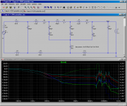
At RF where inductance dominates, inductors in series will act like a voltage divider. That is why the output is flat between 1MHz and 20MHz. All those inductors behave like a set of cascaded voltage dividers. You are also looking at a log scale where every 20db is a factor of 10. -180db is .0000000001V. That's 100pV. RFI will swamp that, and ground noise will probably be even worse. If you increased L6 to 10pH, that would be 1000pV, or -160db.
Of course this behavior will be swamped by load impedance and RFI at the frequencies in question most likely. Every inductance in real life will be picking up EM fields.
Of course this behavior will be swamped by load impedance and RFI at the frequencies in question most likely. Every inductance in real life will be picking up EM fields.
Last edited:
Does it mean that for RF suppression using LRC filter we should realistically aim at 60-80dB noise reduction and no more?
10nH is produced by a 13mm wire which is only the diametre of a 220uF/50V capacitor. All leaded electrolytic capacitors and film capacitors have at least 10nH inductance. If the simulation is correct, 10nH degrades noise filtering by 100dB from 1MHz up.
Unless everything is done with SMD and multilayer PCB, accomplishing anything better than 60-80dB seems to be a remote possibility.
The problem is, SMPS switches between tens of KHz to 2MHz, and produces switching spikes from tens of MHz to 100MHz. The switching frequency will usually not be a problem, but the switching spike frequencies will be. I see NOTHING used on the SMPS board that will stop the switching spikes from getting onto the rails, passing through the regulators, and penetrating into the signal.
I guess that if LRC filters don't work, I must resort to ferrite beads.
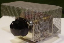
This is one place where the distinction between lossy and lossless components comes in. Capacitors are lossless; they don't dissipate power. They only shunt it from one place to another. Same with inductors. You can move the power away from where you don't want it, but in situations where the air field itself is the main source of noise, the only way to reduce radiation will be to use either lossy filtering to convert the noise to heat, or to use faraday cage shielding. So I would say above 40MHz or so ferrites are mandatory. Have you tried getting aluminum window screening? This is quite malleable for use in shielding. I think they should have it at the hardware store.
Attachments
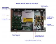
Actually, I forgot to mention in the above picture that there is a ferrite ring surrounding the output cables for the analogue +/-12V power supply output.
I don't know how well this ferrite bead works.
I found the treble is overly exaggerated in this player and usually this is due to high frequency noise.
I don't know how well this ferrite bead works.
I found the treble is overly exaggerated in this player and usually this is due to high frequency noise.
I worry that the ground noise might be a bigger problem than EMI and rail noise. I would try to include some common-mode filtering. However that may ultimately be useless since there are chassis grounding points spattered everywhere. If you are only making partitions, then maybe a double-sided blank PCB would work best. I think VHF filtering should be placed away from lower frequency filtering.
I found all PSU output grounds, including +/-12V for analogue, +12V for mechanicals, +5V for main board, etc, are connected right at the SMPS board, near the output area in a ground plane. They even share tracks before going to the ground plane! The ground must be extremely noiser here.
Interestingly, they then take two separate, long (300mm) wires from the same ground point for the +/-12V DAC power supply on the SMPS board, only rejoin the ground points on the other end in the analogue board.
So according to your theory, we can cut these long wires of 300mm length in the middle, and insert some ground cleaning components, such as common mode chokes, ferrite beads, or LCR to clean up both the ground and the rails?
I can't see why there is common mode noise? I can see differential noise.
I doubt if there are multiple connections / paths between the SMPS ground and analogue board ground. Marantz wouldn't be that stupid. Let us assume that there is a single connection.
We must assume that the cleanest ground must be the analogue ground on the analogue board. In that case, the ground common on the SMPS board is very noisy. How can we prevent the noise from the SMPS ground getting into the analogue board ground? Can we install ferrite beads on the ground wire? Would it work?
I have read of the practice of using ferrite bead to separate digital ground from analogue ground. Some people say yes and some people say no.
Last edited:
Adding filtering to the mechanical and digital parts will decrease the ground noise caused by their return current. However these sources may be tiny compared to the SMPS itself.
You cannot put a ferrite bead on just the ground wire because then the ground noise will just go around it through the decoupling. I am talking about CM noise.
I wonder if there is such a thing as ferrite binding posts for boards that connect to the chassis at their mount points? I suppose any ferrite the right size could accommodate a screw and act as a standoff. What a neat idea.
Does the analogue board have chassis ground connections and if so, where? You say Marantz wouldn't be that stupid yet you are having obvious noise issues. Can the two be reconciled?
OK, I am stupid!
I have just gone to measure the ground connection of the Marantz. There are multiple ground connections.
Right next to the RCA jacks the analogue board ground plane is connected to the chassis.
What is unbelivable is that the SMPS ground plane also connects to the chassis via its binding posts. This is apparently by design, not by accident. I don't mean buidning post, but binding posts, all 4 of them on the ground plane. There are 4 tinted rings surruonding the binding screws to provide contact to the chassis. Wow! the SMPS dirty ground is connected to the chassis, which connects to the analogue board right at the RCA jacks!
I am thinking if I would be mad enough to try removing the SMPS ground connection to the chassis, thinking...thinking...Why does the SMPS ground need to be connected to the chassis? Perhaps in this way, the noise can be reflected away instead of bouncing inside the enclosuer? just pseudo science...
The characteristic impedance of air is about 377R, but will be higher below the wavelength of the frequency in question. If the path from A to be happens to have more than that, then the majority of RFI will travel through the air. This is probably extremely oversimplified but maybe you see my logic.
Perhaps you could construct a second ground plane which connects to the chassis in only one place? Screen door aluminum mesh would work well for this.
Perhaps you could construct a second ground plane which connects to the chassis in only one place? Screen door aluminum mesh would work well for this.
I am trying to improve the sound of a universal disc (blu ray) player powered by a SMPS.
I want to substitue the relatively light weight output LC (after the output regulation stage so it won't alter the control loop or upset the switching operation) on the SMPS board with LRCLRCLRC with small L and tiny R and some ferrite beds so that it can reduce the switching spikes of the SMPS.
<snipped>
Regards,
Bill
Bill,
Have you measured the switching spikes at the point where you think they might do some harm? e.g. between the power rail and ground at an IC power pin?
Do you have high-frequency probe accessories, such as a very short ground foot attachment? An alligator-clip ground wire for the probe won't cut it, and is likely to show spikes that aren't really there.
Do you have some specific reason for believing that voltage spikes are causing an audible problem, in your system? Or do you know of a specific mechanism by which they could cause an audible problem?
If you are looking at power rails for digital ICs, are you SURE that the spikes you see are not being produced by current transients drawn by the IC's power pins, which are then generating voltage spikes across the power rail's inductance, due to insufficient decoupling capacitance or its placement? (You could try connecting a linear PSU, temporarily.)
Have you tried just using a simple CLC pi filter and a linear post-regulator, followed by a reservoir cap, for the DC rail, after the SMPS? (You would need some small R in there, somewhere, probably, for damping.) Maybe something like 1000 uF and 10 to 100 uH. Or skip the first 1000 uF if your SMPS has an output cap.
Have you measured the switching spikes at the point where you think they might do some harm? e.g. between the power rail and ground at an IC power pin?
- I cannot rely on my scope for anything above 10MHz or above. However, see the attached Linear Technology App Note.
Do you have high-frequency probe accessories, such as a very short ground foot attachment? An alligator-clip ground wire for the probe won't cut it, and is likely to show spikes that aren't really there.
- No, as I said.
Do you have some specific reason for believing that voltage spikes are causing an audible problem, in your system? Or do you know of a specific mechanism by which they could cause an audible problem?
- My ears. I have been playing with power supplies a lot and am very familiar with the types of sound when there is mild oscillation, peaking or high impedance on the rails.
If you are looking at power rails for digital ICs, are you SURE that the spikes you see are not being produced by current transients drawn by the IC's power pins, which are then generating voltage spikes across the power rail's inductance, due to insufficient decoupling capacitance or its placement? (You could try connecting a linear PSU, temporarily.)
- I thought of that but chose to try on suppressing the switching spikes first. The problem is that the 8V digital supply is a LDO regulator, as well as the 5V regulator. It is quite risky to do anything on them while not knowing how the regulators behave. It is terribly difficult to improve the digital supply because the LDO regulators have completely different pin arrangements than anything that are commonly available, therefore I cannot swap them easily, then employ low ESL and larger capacitance close to the chips.
Have you tried just using a simple CLC pi filter and a linear post-regulator, followed by a reservoir cap, for the DC rail, after the SMPS? (You would need some small R in there, somewhere, probably, for damping.) Maybe something like 1000 uF and 10 to 100 uH. Or skip the first 1000 uF if your SMPS has an output cap.[/QUOTE]
- The SMPS have all those and more. But at such high frequencies the switching spikes will pass through any regulators and active devices, even the onboard 3.3uH inductors. I think the only things that can stop them are either ferrite beads or air core inductors.
By the way, I have already modified the analogue board by replacing more than some 40 components, and the sound has improved significantly. The power supply mod is the last thing I am doing on the player to get rid of the remaining exaggerated treble sound / high frequency noise.
Attachments
The characteristic impedance of air is about 377R, but will be higher below the wavelength of the frequency in question. If the path from A to be happens to have more than that, then the majority of RFI will travel through the air. This is probably extremely oversimplified but maybe you see my logic.
Perhaps you could construct a second ground plane which connects to the chassis in only one place? Screen door aluminum mesh would work well for this.
In that case, the SMPS ground noise would probably travel via the chassis than air.
Multiple ground paths - is it a bad design from Marantz or I have not learnt enough to understand it?
Without HF measurement capabilities, it will be a little more difficult.
But the options are simple and relatively easy to implement and probably can't do much harm, if they're not effective, except that you could cause unwanted resonances at high frequencies.
Besides ferrite beads (but which ones?!), you should look at the decoupling caps. Id there is an electrolytic there, consider inserting a small resistance in series with it. It could be forming an LC resonance between its parasitic inductance and the small parallel decoupling capacitance that should be near it. You could also check for the possibility of improving the HF decoupliNg capacitance, either by getting it connected closer to the body of an IC or by adding different values in parallel. But remember that a mm of distance from the power pin can make a difference. So obviously the size of the HF decoupling must also be extremely small. However, there might also be intermediate frequencies that are causing problems. Still, it will be difficult to get right, without an RF spectrum analyzer or network analyzer.
A photo of the DAC circuit might be helpful.
Last edited:
Last week I ordered two dozens of Fair-Rite 2773008112 (160R at 20MHz) and 2761008112 (210R at 1GHz, 140R at 100MHz). They don't have in stock 2743008112 (somewhere in the middle of the above two, which would be ideal) so I have not got any. They should arrive within a few days.
I plan to put the 2773008112 and 2761008112 in series and that will cover a wide range from 1MHz to GHz.
I plan to put the 2773008112 and 2761008112 in series and that will cover a wide range from 1MHz to GHz.
There are individual, thin ground wires coming out of the SMPS board going to various other boards. So why do they connect the SMPS ground plane to the chassis?
My guess is that from the SMPS board design, it is apparent that every ground track, be it digital or analogue, are joined at the output of the SMPS board. This is the reference ground of the SMPS. It is the star ground of the SMPS. And it seems that Marantz engineers also chose this star ground of the SMPS to be the reference ground of the entire system as well. The resistance of those output thin ground wires may be high, up to about 0.2R if AWG30-ASW35 wires are used. So the ground noise would be high. Connecting the SMPS star ground to the chassis may reduce the potential between the individual boards and the reference voltage, which may aid in noise reduction and better shielding of EMI.
Now I am really tempted to use Keantoken's idea in page one and use "ferrite binding posts". In other words, I still want to connect the SMPS ground to the chassis, but only at frequencies below 1MHz. Above 1MHz, the ferrite beads will transfer most of the energy into heat. To implement the ferrite binding posts would involve more work, while the simplest way is to insulate the existing binding posts and simply use a wire taking from the SMPS star ground to a single point in the chassis, with some ferrite beads wrapping around the wire.
On top of that, I am thinking about using ferrite beads on every wire going out of the SMPS board, being it rail wires or ground wires.
Keantoken said that ferrite beads should not be used in the ground wires. I cannot think of a reason why not. Below about 1MHz, ferrite beads are like normal wire.
I don't remember where I said not to use beads on ground wires. Ultimately each ground connection has a specific purpose and relationship to all the other ground connections, so the best way to filter noise is not straightforward especially if the conflicting circuits share a chassis or ground plane. The best way that I could think of to do it with least risk was to separate the board from the chassis and use an isolated (by choke, ferrite or insulation) PCB or conductive mesh instead to act as its ground. Then SMPS ground would be separated from other grounds and this would allow CM filtering for the PSU.
- Status
- This old topic is closed. If you want to reopen this topic, contact a moderator using the "Report Post" button.
- Home
- Amplifiers
- Power Supplies
- Is this real? - simulation of parasitics