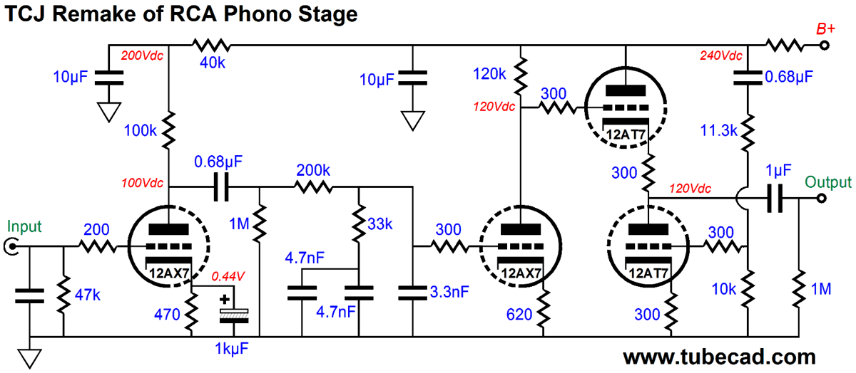
Just thought I'd toss this up here as an option to muddy up the waters, Broskie's take on the RCA phono preamp.
That is maybe a better scheme than i had. Also the Aikido cathode follower is more forgiving to the power supply than the simple cathode follower that i had drawn. Thank you for that, i did not see that yet. But now it's even harder to choose what direction i want to go..
 But i'm learning a lot with this discussion.
I am curious to see whether the plate resistance of a tube changes much through time.
Not so much with time, but with the spread of tube characteristics found these days! I am inenamoured by finding up to 50% differences with e.g. 12AX7s or equivalents.
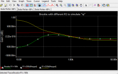
Perhaps splitting hairs as you have shown with the simulation of the RIAA characteristic, but particularly without a build-out resistor as sometimes found, tube distortion also enters the fray with a tube working directly into the varying impedance of an RIAA network - again perhaps small with the small signals encountered, still.
[I might have turned unnecessarily sceptical in my old age, but I hardly design tube pre-amplifier circuits anymore without NFB to restore some predictability of the outcome (see my previous suggestion with a anode-to-previous-cathode kind of feedback topology)].
http://classicvalve.ca/docs/PAS_RCA_Phono_docs.pdf
An externally hosted image should be here but it was not working when we last tested it.
I have an other question (hopefully not to noob).
The last stage is a cathode follower, wich need elevated heater supplies to avoid hum and wear of the tube (vkf of a 12AT7 is 90v, the cathode has 120v, so i need min 30v elevation). I read that you need to supply some dc on the ac heaters of it, but i also read that in a phono preamp, you better only use dc heaters as the amplification is more prone to hum and distortion. Can you elevate dc heater supplies with DC? or is this just for AC heater supplies?
Also it's not fully clear where to tap the dc. I think it's best to do it in the psu on the final B+ (after the filtering) and bring it back to the filament CT, but then all tube heaters are elevated, also the 2 first stages of the preamp. Is that right, and is that a right practice?
).The last stage is a cathode follower, wich need elevated heater supplies to avoid hum and wear of the tube (vkf of a 12AT7 is 90v, the cathode has 120v, so i need min 30v elevation). I read that you need to supply some dc on the ac heaters of it, but i also read that in a phono preamp, you better only use dc heaters as the amplification is more prone to hum and distortion. Can you elevate dc heater supplies with DC? or is this just for AC heater supplies?
Also it's not fully clear where to tap the dc. I think it's best to do it in the psu on the final B+ (after the filtering) and bring it back to the filament CT, but then all tube heaters are elevated, also the 2 first stages of the preamp. Is that right, and is that a right practice?
Last edited:
So, I'm still pretty green when it comes to audio as a whole, but especially tubes. Long time lurker/learner, just starting to find the free time and funding to fiddle!
You can elevate DC heaters, and if you scroll through the link that 6L6 you'll find some info about the TubeCAD PS-10. It outputs regulated DC for heaters and has the option of elevation, searching for "elevated DC heater supplies" will turn up some more examples. Basically (and experts should feel free to jump in and correct me if I'm wrong) on your DC supply you have a positive and negative side after rectification, smoothing, yadda yadda... Instead of grounding the negative side to make a ground referenced supply you let the whole thing float and attach the voltage elevation to the negative side. The supply will be elevated and you will still have 6.3v (or 12.6v) between the two output, it just won't be ground referenced.
As for the tapping the DC, I would place your voltage divider at the final B+, which is commonly how I see it done. You should be fine with [all] the heaters elevated as I you shouldn't be violating any of the vkf values.
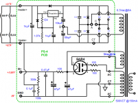
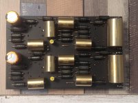
The attached image (taken from PS-4 & PS-5 Tube Power Supplies) gives you another idea on how it's done. The heater supply is left floating, but it is referenced to 85vdc with 12vdc between the two outputs. The Valve Wizard <gives a little more info on elevating heater supplies with AC examples. Morgan Jones' book is also a good resource on this topic, and many other topics.
You can elevate DC heaters, and if you scroll through the link that 6L6 you'll find some info about the TubeCAD PS-10. It outputs regulated DC for heaters and has the option of elevation, searching for "elevated DC heater supplies" will turn up some more examples. Basically (and experts should feel free to jump in and correct me if I'm wrong) on your DC supply you have a positive and negative side after rectification, smoothing, yadda yadda... Instead of grounding the negative side to make a ground referenced supply you let the whole thing float and attach the voltage elevation to the negative side. The supply will be elevated and you will still have 6.3v (or 12.6v) between the two output, it just won't be ground referenced.
As for the tapping the DC, I would place your voltage divider at the final B+, which is commonly how I see it done. You should be fine with [all] the heaters elevated as I you shouldn't be violating any of the vkf values.
The attached image (taken from PS-4 & PS-5 Tube Power Supplies) gives you another idea on how it's done. The heater supply is left floating, but it is referenced to 85vdc with 12vdc between the two outputs. The Valve Wizard <gives a little more info on elevating heater supplies with AC examples. Morgan Jones' book is also a good resource on this topic, and many other topics.
Attachments
I have an other question (hopefully not to noob
The last stage is a cathode follower, wich need elevated heater supplies to avoid hum and wear of the tube (vkf of a 12AT7 is 90v, the cathode has 120v, so i need min 30v elevation). I read that you need to supply some dc on the ac heaters of it, but i also read that in a phono preamp, you better only use dc heaters as the amplification is more prone to hum and distortion. Can you elevate dc heater supplies with DC? or is this just for AC heater supplies?
Also it's not fully clear where to tap the dc. I think it's best to do it in the psu on the final B+ (after the filtering) and bring it back to the filament CT, but then all tube heaters are elevated, also the 2 first stages of the preamp. Is that right, and is that a right practice?
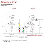
Figure 7 of SY's article: http://www.diyaudio.com/forums/diya...oise-thoroughly-modern-tube-phono-preamp.html
Last edited:
If you want a simple 12AX7 phono stage that still provides good sound quality, try the Shure M65 circuit.
http://www.4tubes.com/SCHEMATICS/Music-amps/Shure/M 65.pdf
http://www.4tubes.com/SCHEMATICS/Music-amps/Shure/M 65.pdf
Looks very nice, and won't break the bank.
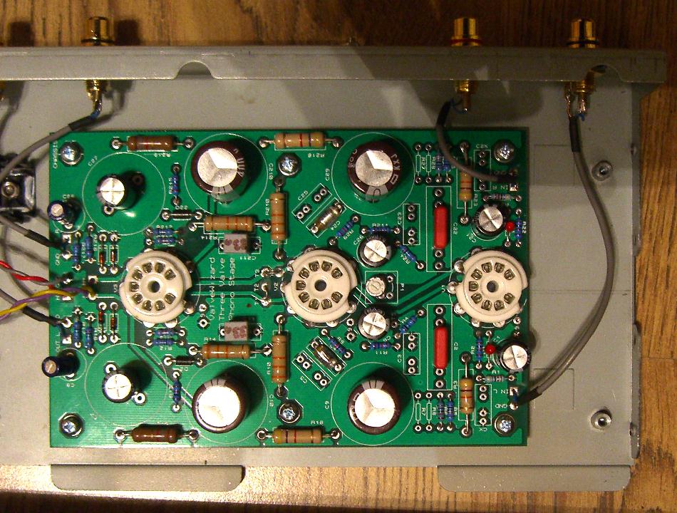
It's funny how people want to push me in directions i don't want to go. I don't want to build a kit or use premade pcb's. I don't want to use transistors or IC's That does not learn me how a tube preamp works. I made kits before and i did not learn a lot from it (except how to solder).
Luckely there are also people who sent me links with a lot of info i can use so i can learn. Thank you for that.
I'm busy with calculating/designing on the TCP adaptation of the RCA RIAA scheme, and found most of the info i needed on the links some of you provided. It's not finished yet (and it may take some time do finish it) but when done i'll post the full scheme so then you can shoot me
Funny you should mention this, it's actually a dynaco PC6 ( phono from PAS3)If you want a simple 12AX7 phono stage that still provides good sound quality, try the Shure M65 circuit.
http://www.4tubes.com/SCHEMATICS/Music-amps/Shure/M 65.pdf
made for shure.
PC6 boards ( or clones ) are available at several places.
But i thing the thread starter want's to build by himself, thus a ready made
card is considered "cheating".
It's funny how people want to push me in directions i don't want to go. I don't want to build a kit or use premade pcb's. I don't want to use transistors or IC's That does not learn me how a tube preamp works. I made kits before and i did not learn a lot from it (except how to solder).
Luckely there are also people who sent me links with a lot of info i can use so i can learn. Thank you for that.
I'm busy with calculating/designing on the TCP adaptation of the RCA RIAA scheme, and found most of the info i needed on the links some of you provided. It's not finished yet (and it may take some time do finish it) but when done i'll post the full scheme so then you can shoot me
Yes , with compensation , phase shifts etc
Note that the Capacitors advance the phase, bobins retard the phase.
Amaze us, use positive feedback, maybe some inductors instead of resistors. and some negative feedback to make a truly good sounding phono stage.
It's funny how people want to push me in directions i don't want to go. I don't want to build a kit or use premade pcb's.
Bravo -- but Merlin is a guru with a couple books to his credit and a JAES article on tube noise, so his work is deemed first rate by many.
FWIW, sometimes I surrender and purchase commercial products! I use SY's "His Majesty's Noise" phono pre, a modded Dyna PAS, and an Adcom GFP-565, but also have a Liberty Audio phono pre which uses JFETs. Whatever it takes to make the music sing!
<snip> so then you can shoot me
As you has been a bit rude with folks who only try to help you, I will be in the front line.
- Status
- This old topic is closed. If you want to reopen this topic, contact a moderator using the "Report Post" button.
- Home
- Amplifiers
- Tubes / Valves
- Is this a good phono preamp circuit to build?