Dear,
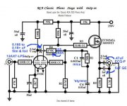
I'm lurking this section of the forum since a longtime and learned a lot. I'm thinking of a first self build phono pre, and after considering many shematics and kits, i found this scheme from Wes Kinsler. It's simple (what i like) and i think it looks good. But as i'm stil a bit a noob on tubes, i would like confirmation that it's worth building it as first tube project. I can't spice it myself as i don't understand the software (yet). So if someone would be so kind to do it for me, i would be very thankfull...
Tube Phono Pre-amp
I can tell i like the sound of 12AX7 based preamps (so if you don't like it, it does not matter for me). I did hear a few and like them more than 6922/6DJ8 based preamps i heared. It will be coupled to a solid state amp first, but the next step after this project will be to build a SE amp as I like those a lot.
The power supply i can design myself, wich will be full DC (also heaters) with heavy filtering and diode rectifiers. I also can get rather cheap but good power toroidials from a friend who winds them as job and hobby.
I'm not an electrician, but i do have a past as soundengineer with a decent basic knowledge of electronics who was not afraid to fix equipment himself, and i do have repaired a few tube compressers, preamps and bass and guitar amps. So working on high voltage stuff is not something new for me.
Last edited:
It's no good.
Input impedance to high for a "normal" cartrige (can be taken care of)
High output impedance, only useful if inside a tube amp (short connection, low load)
For a RIAA correction if the high frequncies are amplified 1x the low side must have a gain of 100x. The max gain with a ECC83 is 100x without load and a CCS on the anode.So for a correct RIAA the second stage has to have a gain of less then 1x high frequency and max gain (=distortion) for the bas.
Between the two triodes is a useless 50Hz filter.
Mona
Last edited:
I can tell i like the sound of 12AX7 based preamps
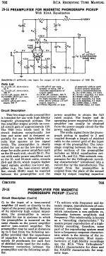
Then build the tweaked RCA setup.
 It has the correct 47 Kohm I/P impedance modern cartridges require and the MOSFET buffer deals with driving loads.
Attachments
The single EF86 RIAA pre amp is simple but excellent.
See Quad II
That does not look like a simple design to me if you mean this one attached. I did already take a look at it, but it's to complex... I could probally build it, but i won't understand what is going on. I'm still learning the thing.
Attachments
Then build the tweaked RCA setup.
This one has a mosfet, and for this project i'm against it. I do have a pacificateur fet preamp that i like and i know fets can do good things. But now i want stricktly tubes, except in the psu where i will use a diode bridge rectifier.
Then use a ecc82 in place of the mosfet. It will be the same circuit.This one has a mosfet, and for this project i'm against it. I do have a pacificateur fet preamp that i like and i know fets can do good things. But now i want stricktly tubes, except in the psu where i will use a diode bridge rectifier.
Then use a 12AT7 as cathode follower in place of the MOSFET source follower.This one has a mosfet, and for this project i'm against it. I do have a pacificateur fet preamp that i like and i know fets can do good things. But now i want stricktly tubes, except in the psu where i will use a diode bridge rectifier.
")
IMO, the FET is superior to a triode, for the buffering role. However, there is no legitimate reason why a DC coupled cathode follower can't be used as the O/P buffer.
As the signal reaching the O/P buffer is already at line level, AC heating is perfectly satisfactory. Use a separate AC supply for the buffer bottle(s) and bias the heater(s) off B+, using a resistive voltage divider, so that the heater is approx. 50 V. positive with respect to the cathode. Such biasing is good for noise control and tube longevity.
As the signal reaching the O/P buffer is already at line level, AC heating is perfectly satisfactory. Use a separate AC supply for the buffer bottle(s) and bias the heater(s) off B+, using a resistive voltage divider, so that the heater is approx. 50 V. positive with respect to the cathode. Such biasing is good for noise control and tube longevity.
IMO, the FET is superior to a triode, for the buffering role. However, there is no legitimate reason why a DC coupled cathode follower can't be used as the O/P buffer.
I know that, i'm looking at that. But the scope of this project is full tube, not mosfets or other solid state devices in the audio path. I may replace it with an ECC82, but now i'm also looking at the Marantz 7C scheme, wich is more the direction i want to go. That seems to be a proven design and oldskool, like what i want to build now.
I alredy have a DIY FET phono preamp, wich i like, now i want a totally different character, that's why i'm looking at older designs and tubes only (except psu). I know the disadvantages of those, but for some things these are also a benefit.
And next to the sound i'm searching, i also want to learn more about tube amp design in general. This forum helps a lot with that, so thanks, also for the posts that were not what i'm searching.
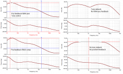
positive feedback for RIAA compensation has been around since the 1950's. hold your breath, they easily become unstable. i built a similar circuit from an AudioXpress article (Titschler, commercial product here: Tritschler Precision Audio Devices, a/k/a TPAD! Brought to you by DoctorCrazyJoe.com and Tritschler Precision Engineering!)
I think the design needs some work, the result from the circuit presented in the first post differs significantly from correct compensation, here are some bode plots with the circuit dissected:
I think the design needs some work, the result from the circuit presented in the first post differs significantly from correct compensation, here are some bode plots with the circuit dissected:
Attachments
Tritschler has the original article archived on their site:
http://doctorcrazyjoe.com/images/tpad/aX October 2003.pdf
update:
http://doctorcrazyjoe.com/images/tpad/aX January 2010.pdf
This will behave well, the 5842/417A tubes are a bit difficult to source, but you can use d3A wired as triode (and others)
http://doctorcrazyjoe.com/images/tpad/aX October 2003.pdf
update:
http://doctorcrazyjoe.com/images/tpad/aX January 2010.pdf
This will behave well, the 5842/417A tubes are a bit difficult to source, but you can use d3A wired as triode (and others)
i would like confirmation that it's worth building it as first tube project.
With their good suggestions and also some analysis of the circuit, the knowledgable people responding to this thread are gently telling you that the circuit probably is not a good candidate for a first time build.
My reservations are simple - the output is taken off the plate of the 2nd stage, in addition to a feedback circuit, and the AX7 will be completely taxed in current and will have an extremely hard time driving any cable, a pot and a gain stage after that. Those poor driver characteristics, the possibility of instability due to the positive feedback configuration, and the poor RIAA conformity makes many other circuits a much better choice.
At the minimum, you'll need to add a cathode follower on the output.
My advice is to build the circuit Eli Duttman suggested - it's stable, accurate, known to work, has a large about of builders on the site who can help if you get stuck or need assistance, and I've never read anything other than wonderful success and sound from those who have built it. The Mosfet follower, because it's a follower, is sonically invisible, and will help the circuit integrate into whatever system you choose, as it can drive anything.
Last edited:
With their good suggestions and also some analysis of the circuit, the knowledgable people responding to this thread are gently telling you that the circuit probably is not a good candidate for a first time build.
My advice is to build the circuit Eli Duttman suggested - it's stable, accurate, known to work, has a large about of builders on the site who can help if you get stuck or need assistance, and I've never read anything other than wonderful success and sound from those who have built it. The Mosfet follower, because it's a follower, is sonically invisible, and will help the circuit integrate into whatever system you choose, as it can drive anything.
I'm going back to the original RCA RIAA scheme i think, and skip the mosfet and replace it with a tube. I found the original scheme, and that looks very good. It's also a proven scheme with lots of info about the technical side. So on that level i follow you. But i want no mosfet or other semiconductor that is not a tube in the scheme. That is not going to change because many like it here. I've red all your discussions about it and i understand why you want it, but it's not what i want as explained above.
About the first scheme, i got the point, it's not wel constructed and difficult to build it so it would work, so i won't consider it anymore.
I suspect that the RCA with a tube cathode follower has been built, with great success, and somebody has the schematic written down.
Anybody?
Wel, this is what i found somewhere (diyaudioprojects). I'm still studying the scheme to see if it's right... But i rather want to use a MM cartridge so i need to find out how to lower the gain i suppose... Maybe with replacing the second 12AX7 stage by an ECC82/12AU7 like suggested above.
Attachments
Last edited:
This phono is made for a MM. Don't spoil a good design !Wel, this is what i found somewhere (diyaudioprojects). I'm still studying the scheme to see if it's right... But i rather want to use a MM cartridge so i need to find out how to lower the gain i suppose... Maybe with replacing the second 12AX7 stage by an ECC82/12AU7 like suggested above.
Have you seen the 150x gain ? With 5mV from the cartrige the output is only ¾volts , what do you mean, lowering the gain ?Wel, this is what i found somewhere (diyaudioprojects). I'm still studying the scheme to see if it's right... But i rather want to use a MM cartridge so i need to find out how to lower the gain i suppose... Maybe with replacing the second 12AX7 stage by an ECC82/12AU7 like suggested above.
And on an output "minimum load 200000ohm"
.Mona
- Status
- This old topic is closed. If you want to reopen this topic, contact a moderator using the "Report Post" button.
- Home
- Amplifiers
- Tubes / Valves
- Is this a good phono preamp circuit to build?