Well, the idea is quite simple...If you are building a say, 4-channel amp (stereo bi amp), the eBay kits cost ~$32. If you go the neurochrome route, you're at $300 JUST FOR THE BARE BOARDS AND PLANS. Now, paying extra for a superior design is all well, and good. But an extra $260 (say the boards are $20 apiece) is HIGHWAY ROBBERY!! HALF that would be a steep price---maybe worth it.
I suggest you look at what it costs to run a business. Development cost, prototyping cost, manufacturing cost, parts cost, cost of test equipment and keeping it calibrated, taxes, etc. That's not counting the 10+ years of university level education, 10+ years of industry experience in precision DC circuit design, and 35+ years of hobby experience that you benefit from when buying my products.
Neurochrome is my only source of income (by choice) and I'm making less than half of what I would make if I worked for someone else. I'm having lots more fun too, so I'm not complaining, but I'm not exactly rolling in cash here. I'd like to retire some day. Neurochrome is not likely to help me much in achieving that goal.
What you get when you buy from me is state of the art performance. There's one commercial company (Benchmark) that has a product (ABH-2) with performance rivalling that of my Modulus-86. The ABH-2 is $3k. You can build a stereo Modulus-86 for about $400, including chassis. I consider that a downright steal.
I'm not forcing you to buy. If you don't like my pricing or what I have to offer, there's always eBay.
Tom
I suggest you look at what it costs to run a business. Development cost, prototyping cost, manufacturing cost, parts cost, cost of test equipment and keeping it calibrated, taxes, etc. That's not counting the 10+ years of university level education, 10+ years of industry experience in precision DC circuit design, and 35+ years of hobby experience that you benefit from when buying my products.
What you get when you buy from me is state of the art performance. There's one commercial company (Benchmark) that has a product (ABH-2) with performance rivalling that of my Modulus-86. The ABH-2 is $3k. You can build a stereo Modulus-86 for about $400, including chassis. I consider that a downright steal.
I'm not forcing you to buy. If you don't like my pricing or what I have to offer, there's always eBay.
Tom
Dont get sucked in Tom. We all know what it takes tp do what youve done. People get jealous sometimes, why not be happy for someone that prides themselves on quality.
Thanks. Yeah... Some can't afford to spend $400 on a DIY product. That leads to envy or jealousy. I get that. That's not my problem to fix. I have real expenses (such as the $2700 I spent getting a digital I/O installed on my APx525 and getting it calibrated). AP doesn't work for free. Weird... Shame on them! ")
Tom
Tom
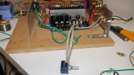
Maverick, back to correctly installing your amp. Near the fan connector on the amp board, you can see a chassis/ground symbol for the mounting hole. This is where the amp should be connected to the chassis. Connect the mains PE to the chassis and if available the transformer shield should also be connected to the chassis. All the other chassis connections are wrong and should be removed.
Ok thanks I will give it look tonight. I like the idea of extending the pot, but it will take some engineering.Maverick, back to correctly installing your amp. Near the fan connector on the amp board, you can see a chassis/ground symbol for the mounting hole. This is where the amp should be connected to the chassis. Connect the mains PE to the chassis and if available the transformer shield should also be connected to the chassis. All the other chassis connections are wrong and should be removed.
I patched in the 10k ALPS Pot as per picture, thanks.
I used single core shielded wire.
Its a rough solder job but it works. Is there some special connections or something that will look neater for connecting the pot also the 3 pin (L-G-R) input onto the board where can i find a plug like this?
The his has gone and no issues at all. I will now revisit my grounding points now.
Attachments
Maverick,
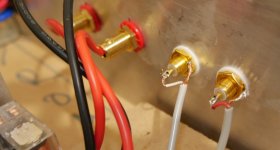
the core of the screened cable is exposed where you have stripped back the screen/shield.
This termination has a big loop area.
You can improve this a lot.
Strip off a bit more outer insulation and screen to make a longer pigtail.
Shorten the core to leave the minimum sticking out from the screen.
Attach that core on to the Hot terminal. Add some insulation around that terminal.
Now run the pigtail along side the hot terminal almost touching the core&terminal.
Solder the pigtail to the end of the threaded shield. If you pre-solder that end it will be easier to attach the pigtail. Make the LOOP AREA between the very short core and the shield wiring as small as possible.
This minimises interference.
Repeat this low loop area termination at every two wire signal connection, even speakers and PSU need this to minimise EMI.
Last edited:
Im confused, do you have photos? ThanksMaverick,
the core of the screened cable is exposed where you have stripped back the screen/shield.
This termination has a big loop area.
You can improve this a lot.
Strip off a bit more outer insulation and screen to make a longer pigtail.
Shorten the core to leave the minimum sticking out from the screen.
Attach that core on to the Hot terminal. Add some insulation around that terminal.
Now run the pigtail along side the hot terminal almost touching the core&terminal.
Solder the pigtail to the end of the threaded shield. If you pre-solder that end it will be easier to attach the pigtail. Make the LOOP AREA between the very short core and the shield wiring as small as possible.
This minimises interference.
Repeat this low loop area termination at every two wire signal connection, even speakers and PSU need this to minimise EMI.
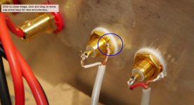
I dunno Andrew. It's hard to get it much tighter than what Maverick's done. You might be able to reduce the loop a bit by letting the centre conductor exit straight from the cable jacket and bringing the shield to the solder lug as close to the centre conductor as possible (insulate with heat shrink tubing). I'm pretty sure any improvement that's obtained there is firmly below the 0 dBGF reference level. That's dB relative to one imperial Gnat Fart.
The shield on the white RCA connection is barely hanging onto the solder lug, though. That's a bigger issue. If that lets go, the amp could do nasty things to the speaker. I'd fix that. Get some heat into that solder lug.
Tom
The shield on the white RCA connection is barely hanging onto the solder lug, though. That's a bigger issue. If that lets go, the amp could do nasty things to the speaker. I'd fix that. Get some heat into that solder lug.
Tom
Attachments
Last edited:
Don't worry about it, seriously it's fine, it's not a big issue, reallyIm confused, do you have photos? Thanks
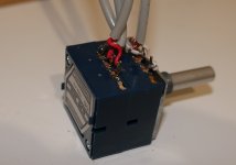
Did you add thermal compound between the chips and heatsink? Without it, the chips will not last long, as they are not conducting heat very well.
Not yet. I will have to pick some up. So far I havent really had it on for too long. Thanks for the help.
When I was young and paranoid for such things (that's to say some decades ago...It's hard to get it much tighter than what Maverick's done. ...
), I used two extra washers to fix the "cold" solder tag back to the end of the threads, right beside the hot pin. Don't know if there was some contact quality penalty with that arrangement, but it sure was MUCH tighter than anything else.Now I'm older and too lazy for this kind of stuff though...
This was a quick test this setup. I done it quickly before bed last night.I was referring to the wiring around the RCA jack being about as tight (tidy, short, neat) as can be. Not the nut on the RCA jack.
The solder joint to the grounding lug on the white side is my concern.
Tom
So should i feed the shield earth through and twist then solder? Then have enough wire expose to loop around to the rca pin?
Whats the best way to connect the pot with wires? Im thinking if using a blank universal pcb and cut it down.
My wrong use of language, sorry.I was referring to the wiring around the RCA jack being about as tight (tidy, short, neat) as can be. Not the nut on the RCA jack....
Correct: "I used two extra NUTS to bring the "cold" solder tag back to the end of the threads" (tightened between the two nuts)
This way, just a couple of millimeters separated it from the hot pin, allowing for really tight, neat and safe wiring
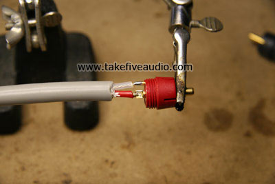
Here's my procedure:
1) Start by draping a piece (20 mm) of heat shrink tubing over the coax cable.
2) Strip the coax cable so you have about 25 mm of shield showing. Unbraid the shield and twist the strands together.
3) Drape a small (5-6 mm) piece of heat shrink tubing over the shield and shrink it using a heat gun.
4) Cut off about 12 mm of the centre conductor.
5) Strip the centre conductor so you have 4-5 mm of the copper strands showing. Twist the strands together and tin them.
6) Feed the shield through the hole in the grounding lug and solder the centre conductor to the centre of the RCA connector. Then solder the shield.
7) Slide the heat shrink tubing applied in Step 1) so it drapes over the end of the coax outer jacket. Shrink using a heat gun.
This is the best image I could find. You want the shield and centre conductor to run parallel for as long as you can with as small a gap between them (the small loop area that Andrew talked about) as you can.
Tom
My wrong use of language, sorry.
Correct: "I used two extra NUTS to bring the "cold" solder tag back to the end of the threads" (tightened between the two nuts)
This way, just a couple of millimeters separated it from the hot pin, allowing for really tight, neat and safe wiring
Interesting approach. I think that's a bit overkill, but if it makes you happy...
Tom
Tom,
Your approach is pretty neat, but you use a different type of RCA jack which allows it to happen.
With the ones Maverick uses, pictured in your post #70, what do you do? You bring that return contact right at the back, and bend it parallel to the hot pin. Then proceed as you described.
This stuff did made me happy back then, but repeat, now I am turning lazy
- Status
- This old topic is closed. If you want to reopen this topic, contact a moderator using the "Report Post" button.
- Home
- Amplifiers
- Chip Amps
- Is this a good LM3886 Kit?