juma: Seems I'm out of 1k SMD resistors, although I can try salvaging some from the old boards. But I have plenty of 1k2, which I could use if I can't save any 1k. What do you think about putting 1k2 in for R5 and R14? In the case of R14 it should raise the gate-source voltage on Q4, and hence increase current through the jfet, which we don't really want from the heat point of view, but at least R12 lets us fix voltages (right?). I am less sure of what happens with R5. This is part of a feedback loop (?) so R6 probably sets gain, but what about 1k2 for R5?
Sorry if that all sounds a little confused. Still trying to figure all this out.
Cheers
Nigel
Sorry if that all sounds a little confused. Still trying to figure all this out.
Cheers
Nigel
Wait a minute... What I wrote about R14 is rubbish... Vgs is *fixed* by the device's characteristics (right?) so R14 is just to make sure there is enough voltage at gate, so raising it to 1k2 should make no difference. (?) Please correct me if this is (again) rubbish... 
Cheers
Nigel
Cheers
Nigel
Ratio R6/R5 sets the gain of the amp (G=R6/R5 + 1), so higher R5 means less gain...What do you think about putting 1k2 in for R5 and R14? ...
R14 is a gate stopper - can be anything from 100R to 1k2 or 1k5 or you can leave it out (it's there to stop possible oscillations - which are not likely to happen here)
Vgs of the JFET is the value that you set with source resistor (R13) in order to set the Id through JFETVgs is *fixed* by the device's characteristics (right?)
Last edited:
Ratio R6/R5 sets the gain of the amp (G=R6/R5 + 1), so higher R5 means less gain
R14 is a gate stopper - can be anything from 100R to 1k2 or 1k5 or you can leave it out (it's there to stop possible oscillations - which are not likely to happen here)
Vgs of the JFET is the value that you set with source resistor (R13) in order to set the Id through JFET
OK, I'll get this stuff eventually...
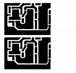
In this case, almost no voltage drop over R14, so Vgs is almost the same as voltage across R13... For R5 I really ought to try to salvage at least two of the 1ks from the old boards... with eight candidates to try should be possible... (Although a change from gain of 11 to 9.3 isn't such a big deal, probably...) Meanwhile, I have new board designs, this time with R10 and R11 on the sources of the jfets... Posted below, if anyone is interested. (Copy for printing is a little cleaner than the upload...) I decided if it's worth doing everything from scratch then I might as well get the details right too...
I have a day off work with the kids in school so I can play with this a little...
Cheers
Nigel
Attachments
That's how it should be, we don't want any current flowing in to the GateOK, I'll get this stuff eventually...
Not a big deal at alla change from gain of 11 to 9.3 isn't such a big deal, probably...
Just take it easy, don't let some hectic action force you to do it one more time
Just take it easy, don't let some hectic action force you to do it one more time
Yeah, no kidding ....
Hi everyone,
I have the amp rebuilt, and working again. Hooray! It sounds great.
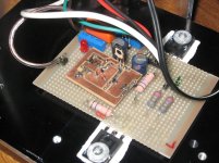
I have attached a photo showing one of the new(est) boards installed - you can see the new board layout quite clearly - larger copper areas, and R1 is not SMD (although it *is* surface-mounted, in a sense) for easy change of value should it be needed. You can also just see the second trimpot I put in for R15.
As far as values go, I used the schematic from post #53, with the only differences being R1 at 560R and R7/R16 at 0R56, and only 1uF across the LED. I set the trimpot for R15 to 68k before installing it, and have moved it little; the trimpot R12 was set to 56R, but adjusting for DC offset has put it around 85R.
Other values: voltages across R10 and R11 are both 80mV, so 8mA going through each side of the LTP - right about where we want it. Confirmed by 4.53V on R1. (560R x 0.008A = 4.48V...) R13 shows 371mV, which is 6.6mA - a little higher than the 4-5mA that juma recommended, but it has about a square centimetre of "heatsink" area on the gate pin, so probably OK. I can probably switch R13 for 100R as juma suggested to reduce this, if necessary, but nothing appears to be getting too outrageously hot at present.
R7 and R16 show 531mV and 545mV, so bias current is just under 1A. Stable heatsink temp is 50 deg C.
Only things that aren't fine are the DC offset at turn-on and the thump on turn-off. The DC offset is initially quite high (momentarily about 1/2 V, falling in 2 secs to about 150-200mV, and falling in the next 20-30 secs to reasonable. At stable temp the offset is negligible- around 10mV or less... I haven't fiddled with this too much yet, so I can probably improve it a little, but I have a question here. When juma suggested putting in a trimpot for R15, it was to "fine-tune" the offset. Am I right in thinking I should alter R12 principally, and only do the last bit with R15? Does anyone think 85R on R12 is too high? (I don't see any reason to think so - just a notable difference from the original specs.)
The thump is a little more worrying. It is not loud enough to be a problem for the present speakers, but might be if I get something better... (Maybe will bring me a pair of Sonidos?) On a multimeter this can be seenas a surge of well over 1V as the PSU is switched off. Anyone have any suggestions? Are the two problems maybe linked?
Anyhow, many thanks.
Cheers
Nigel
I have the amp rebuilt, and working again. Hooray!
It sounds great.I have attached a photo showing one of the new(est) boards installed - you can see the new board layout quite clearly - larger copper areas, and R1 is not SMD (although it *is* surface-mounted, in a sense) for easy change of value should it be needed. You can also just see the second trimpot I put in for R15.
As far as values go, I used the schematic from post #53, with the only differences being R1 at 560R and R7/R16 at 0R56, and only 1uF across the LED. I set the trimpot for R15 to 68k before installing it, and have moved it little; the trimpot R12 was set to 56R, but adjusting for DC offset has put it around 85R.
Other values: voltages across R10 and R11 are both 80mV, so 8mA going through each side of the LTP - right about where we want it. Confirmed by 4.53V on R1. (560R x 0.008A = 4.48V...) R13 shows 371mV, which is 6.6mA - a little higher than the 4-5mA that juma recommended, but it has about a square centimetre of "heatsink" area on the gate pin, so probably OK. I can probably switch R13 for 100R as juma suggested to reduce this, if necessary, but nothing appears to be getting too outrageously hot at present.
R7 and R16 show 531mV and 545mV, so bias current is just under 1A. Stable heatsink temp is 50 deg C.
Only things that aren't fine are the DC offset at turn-on and the thump on turn-off. The DC offset is initially quite high (momentarily about 1/2 V, falling in 2 secs to about 150-200mV, and falling in the next 20-30 secs to reasonable. At stable temp the offset is negligible- around 10mV or less... I haven't fiddled with this too much yet, so I can probably improve it a little, but I have a question here. When juma suggested putting in a trimpot for R15, it was to "fine-tune" the offset. Am I right in thinking I should alter R12 principally, and only do the last bit with R15? Does anyone think 85R on R12 is too high? (I don't see any reason to think so - just a notable difference from the original specs.)
The thump is a little more worrying. It is not loud enough to be a problem for the present speakers, but might be if I get something better... (Maybe
will bring me a pair of Sonidos?) On a multimeter this can be seenas a surge of well over 1V as the PSU is switched off. Anyone have any suggestions? Are the two problems maybe linked?Anyhow, many thanks.
Cheers
Nigel
Attachments
Praise the Lord !Hi everyone,
I have the amp rebuilt, and working again. Hooray!
1V over 8 ohm speaker is 125mW - get over it...On a multimeter this can be seen as a surge of well over 1V as the PSU is switched off.
Congratulations on your new amp!

Praise the Lord !
1V over 8 ohm speaker is 125mW - get over it
Congratulations on your new amp!
Thanks for all the help, juma...
Cheers
Nigel
On a multimeter this can be seen as a surge of well over 1V as the PSU is switched off.
I would imagine that the actual peak is a bit larger than the value indicated by a DMM. It may be prudent to look at that on a scope, if you can.
I would imagine that the actual peak is a bit larger than the value indicated by a DMM. It may be prudent to look at that on a scope, if you can.
Well, I don't have access to a scope, unfortunately. I am fiddling with using a computer sound card and a software oscope program, but so far I can't get it to work. And in any event, it may not be the best idea to try to measure a dc thump with a sound card.... To say the least...
Unless anyone has any suggestions I'm just going to live with the thump, for the time being, and look into dc protection circuits for if/when I get better speakers to use with it.
Cheers
Nigel
Hi Nigel,
please remove any cap from CCS (I think you got just one 1uF parallel to LED) and see what does it do for turn-on/off thump.
juma: Following your suggestion I've pulled out the 1uF caps (C2 - in your schematic from post #53 they are 22uF). No appreciable audible difference in the thump. I also tried it with no speakers and just the a DMM on each channel. On the 20V scale there isn't enough time for the meters to react properly; on the 2V scale they flash above 2V momentarily. I don't think the thump is loud enough to damage the cheapo speakers I'm using at present, it would mostly be a problem if I build something better for my office.
CHeers
Nigel
believe me - even if it sounds scary - even delicate Lowthers can't be harmed with Aleph J's thump .
not that I'll tell you that decent DC protection & anticlick will harm anything .
if you have any decent speakers - that is must .
Hi ZM. I'm looking at some info on DC protection I got from another forum member to try and figure out what to do about DC protection. Do you have any links or schematics you could suggest?
Cheers
Nigel
Nigel,
How is the amp treating you? You had said the sound was OK. Any better now? Can you compare it to any other amps you have built?
Uriah
Hi Uriah,
I put some observations of the sound in post #58. That was the first version of the amp, before blowing it up by fiddling around, and then rebuilding it... (Whole story is above, if you're interested.) I am using the amp on a daily basis, and am very pleased with it. Since last posting I have added a speaker protection circuit and relays, but otherwise the circuit is the one decribed above, although with IRFP9140s in place of the dead IRFP9240s.
I am using it in my home office, with a diy B1 most of the time, although that will shortly be replaced by a BF862 symmetrical "B1". I think I may repeat the comparison with the F5 in the living room, since I now have juma's BF862 preamp running there, but I see no reason to think my overall impression has changed from post #58. (If it does, I'll post...)
To give you a reference, the other amps I have built are: LM3876 chip amp, 3 versions of Hiraga's Le Monstre (with modern equivalents for the parts, not the orignals), Hiraga's 20W Le Class A, a scaled-down F4 (which has given trouble, so I will exclude it from the comparisons) and the F5 in the living room. (I also have an old, and now largely retired, Creek 5050 integrated amp). Of these only the F5 compares well with the amp in question. (Obviously the F5 is more powerful - I've done my best to compare at similar levels.) As I wrote above, I am fascinated by the slight warmth in the treble that I felt I heard in this compared to the slightly more clinical sound in the F5 - perhaps this is the sound of a SE amp as compared to a symmetric design like the F5?
Anyway, lacking any measuring equipemt like an oscilloscope, I can only give you these subjective opinions. If you have any specific question that I can answer without an oscope please let me know. I highly recommend the amp, and would be fascinated to hear about your experiences if you decide to build one.
Cheers
Nigel
P.S. I see I promised in post #58 to "report more extensively"... Sorry for the delay!
- Status
- This old topic is closed. If you want to reopen this topic, contact a moderator using the "Report Post" button.
- Home
- Amplifiers
- Pass Labs
- Is a mini-Aleph using BF862 possible?