....for cheap and hilarious good ( for my ears - better than many Lowthers ) - see FR drivers at Sonido akusztika
ZM: Apparently the site hasn't been modified since 2006... Are they still in business? I couldn't understand the pricing in Hungarian (no surprise there), and the English pages have no prices... What sort of $$$ are we talking here? I'm mostly interested in the smaller FRers. (May be beyond my budget anyhow, especially after paying the &*%$#@$%@ Brazilian import taxes... we'll see.)
They actually look really nice, although what they look like isn't the point really, I suppose...
")
Cheers
Nigel
ZM: Apparently the site hasn't been modified since 2006... Are they still in business? I couldn't understand the pricing in Hungarian (no surprise there), and the English pages have no prices... What sort of $$$ are we talking here? I'm mostly interested in the smaller FRers. (May be beyond my budget anyhow, especially after paying the &*%$#@$%@ Brazilian import taxes... we'll see.)
They actually look really nice, although what they look like isn't the point really, I suppose...
Cheers
Nigel
sorry - I didn't realized that you're in Maracana country ... so it's certainly easier to buy them in any EU contry .
anyway - there is (only in Hungarian language ) price list :
Sonido - árlista
to save you translation and converting ......
SFR144-8 - 17.800Ft - 67E
SFR177-8 - 26.300Ft - 99E
SFR200-8 - 35.700Ft - 135E
all prices per piece
information is not there , but they also have - at least for 200mm driver - AlNiCo version for aprox. same money , and they also have SWR200-8A (AlNiCo) version , made for either BR , or Onken cab .
I have that - last one and hope to try them soon in ML TQWT
my friend spavleski have smallest - SFR144-8 in BLH cab made from plans from Sonido site , driving them with Babelfish J ....... and that's absolutely gorgeous sound
edit : they're in biz fer sure ; just send them a mail - Varga Junior is fluent in English
Last edited:
sorry - I didn't realized that you're in Maracana country ... so it's certainly easier to buy them in any EU contry .
anyway - there is (only in Hungarian language ) price list :
Sonido - árlista
to save you translation and converting ......
SFR144-8 - 17.800Ft - 67E
SFR177-8 - 26.300Ft - 99E
SFR200-8 - 35.700Ft - 135E
all prices per piece
information is not there , but they also have - at least for 200mm driver - AlNiCo version for aprox. same money , and they also have SWR200-8A (AlNiCo) version , made for either BR , or Onken cab .
I have that - last one and hope to try them soon in ML TQWT
my friend spavleski have smallest - SFR144-8 in BLH cab made from plans from Sonido site , driving them with Babelfish J ....... and that's absolutely gorgeous sound
edit : they're in biz fer sure ; just send them a mail - Varga Junior is fluent in English
Thanks ZM - I'll send them some email and see what the chances are of getting them shipped here. The prices don't look too bad at all - certainly more accessible than Lowther prices...
Thanks again
Nigel
Possible rebuild
juma:
Last night I tracked down a strange noise in on channel, and found that
the little wire heatsinks I put on were pulling the tracks off the pcb. I've fixed the problem temporarily by putting a lighter wire on, but I am considering doing new boards, a little larger, and leaving copper areas on the gates that are large enough to dissipate the heat, so that the wires are not needed. If I decide to do this then I could take the opportunity and change some component values around, if I wished. So since you built the circuit with other values as you write above, closer to Nelson's values for the Aleph-J, I wanted to ask if you felt there was any particular advantage compared to your original circuit.
I still think the amp sounds good, by the way, although more serious evaluation needs better speakers. I am having a little trouble with dc offset on startup; I am wondering if thermal coupling (or lack of it) is the cause - things seem to be fine once the amp gets hot.
Cheers
Nigel
I've sketched a new layout for the boards, which gives a good more real estate to the gates on the jfets. I haven't written on it which comipoents are which, but the only change from the last one are the obvious big black "heatsink" blocks. Comments?
Cheers
Nigel
Cheers
Nigel
Attachments
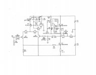
I wouldn't call it "my" circuit- I just modified well known Aleph-J in order to use BF862 in LTP. Some values used in 1st sch. are adjusted for lower PS voltage (+/-15V or so) but since you moved higher (was it +/-19V?), why not use what Mr. Pass uses - he surely tested them thoroughlyjuma:
....since you built the circuit with other values as you write above, closer to Nelson's values for the Aleph-J, I wanted to ask if you felt there was any particular advantage compared to your original circuit. ....
When it comes to LTP and its' CCS the changes were necessary to accommodate BF862.
Don't worry too much about it, it's OK the way it is now
I've sketched a new layout for the boards, which gives a good more real estate to the gates on the jfets. I haven't written on it which comipoents are which, but the only change from the last one are the obvious big black "heatsink" blocks. Comments?
Looks nice, just be sure to use good quality PCB board (cooler wires or not, tracks that peel off are sign of bad quality/too much messing with the board)

I wouldn't call it "my" circuit- I just modified well known Aleph-J in order to use BF862 in LTP. Some values used in 1st sch. are adjusted for lower PS voltage (+/-15V or so) but since you moved higher (was it +/-19V?), why not use what Mr. Pass uses - he surely tested them thoroughly
When it comes to LTP and its' CCS the changes were necessary to accommodate BF862.
Don't worry too much about it, it's OK the way it is now
Thanks juma, maybe I'll do something a little closer to the second circuit (the one you built)...
Looks nice, just be sure to use good quality PCB board (cooler wires or not, tracks that peel off are sign of bad quality/too much messing with the board)
Well, I'm stuck with using the quality of board I can get - I have nothing to compare it with to know whether it's bad or not... Tracks peeling off is probably more due to my messing around with the board than its quality, anyhow...
Thx again!
Nigel
Here's an update for anyone following this...
I did the new boards, using the design I posted above, doing everything on the PCB from scratch, new jfets, matched them again and so on. I made some changes, specifically, 470R gate resistors on the LTP and a 22uF electrolytic in for C2 (actually in parallel with the 1uF MKT I had in before, so 23uF...), as per the circuit juma built. I was planning on altering the Aleph current source also, but a lack of 68k and 3.3k resistors in my parts box combined with a lack of energy to go out and buy some stopped that...
(juma: How did you choose the value of C2? There's a big difference between 1uF and 22uF, so I guess it can't be critical...)
Everything is back together and working well, without the wire heatsinks at present. I have been following the temperature on the copper patches on the boards, and it looks like the temperature of the gate soldering points stabilises at 60 deg. C. Since the datasheet for the BF862 says that the difference between junction and gate goes up at 200 deg./W, and the jfets are dissipating 190mW, that gives just short of 100 deg. C for junction temp, where the device is "safe" to 150 deg. C. I think this is probably OK, but a little too hot for comfort. Since the copper patches are mechanically much stronger than the traces I had before, I can probably put the wire heatsinks back on if necessary, without repeating the previous problems... but I am unsure whether it is worth it, especially since it makes the boards uglier (not very important) and difficult to manage when making component changes (somewhat more important)... Opinions?
Another small irritation is that the DC offset is "twitchy". When the amp is cold it is quite high (2OOmV or so, dropping fast) and settles to small (jumping around about +/- 10 - 15 mV) when hot. However, when trying to adjust it a very small adjustment in the trimpot makes the DC jump quite a bit, and not always the same way... After a little perserverance and things are OK, but I'd like to understand it better. Do other Aleph versions have this? Is it normal for SE designs? (The other amps I have done are all symmetrical designs like the F5). Is it possible that having different values for R7 and R16 makes this worse?
I also have a thump on turning the amp off (but not turning it on...) Watching this on a voltmeter shows about 1.2 Vdc coming through as a transient. It doesn't seem bad enough to damage the speakers I have at present, but might be an issue if I upgrade to something fancier.
(ZM: Talking about something fancier, I sent email inquiring about the Hungarian drivers - no reply yet, but I'm wondering if Santa will be kind this year... )
As always, thanks for any help.
Cheers
Nigel
I did the new boards, using the design I posted above, doing everything on the PCB from scratch, new jfets, matched them again and so on. I made some changes, specifically, 470R gate resistors on the LTP and a 22uF electrolytic in for C2 (actually in parallel with the 1uF MKT I had in before, so 23uF...), as per the circuit juma built. I was planning on altering the Aleph current source also, but a lack of 68k and 3.3k resistors in my parts box combined with a lack of energy to go out and buy some stopped that...
(juma: How did you choose the value of C2? There's a big difference between 1uF and 22uF, so I guess it can't be critical...)
Everything is back together and working well, without the wire heatsinks at present. I have been following the temperature on the copper patches on the boards, and it looks like the temperature of the gate soldering points stabilises at 60 deg. C. Since the datasheet for the BF862 says that the difference between junction and gate goes up at 200 deg./W, and the jfets are dissipating 190mW, that gives just short of 100 deg. C for junction temp, where the device is "safe" to 150 deg. C. I think this is probably OK, but a little too hot for comfort. Since the copper patches are mechanically much stronger than the traces I had before, I can probably put the wire heatsinks back on if necessary, without repeating the previous problems... but I am unsure whether it is worth it, especially since it makes the boards uglier (not very important) and difficult to manage when making component changes (somewhat more important)... Opinions?
Another small irritation is that the DC offset is "twitchy". When the amp is cold it is quite high (2OOmV or so, dropping fast) and settles to small (jumping around about +/- 10 - 15 mV) when hot. However, when trying to adjust it a very small adjustment in the trimpot makes the DC jump quite a bit, and not always the same way...
After a little perserverance and things are OK, but I'd like to understand it better. Do other Aleph versions have this? Is it normal for SE designs? (The other amps I have done are all symmetrical designs like the F5). Is it possible that having different values for R7 and R16 makes this worse? I also have a thump on turning the amp off (but not turning it on...) Watching this on a voltmeter shows about 1.2 Vdc coming through as a transient. It doesn't seem bad enough to damage the speakers I have at present, but might be an issue if I upgrade to something fancier.
(ZM: Talking about something fancier, I sent email inquiring about the Hungarian drivers - no reply yet, but I'm wondering if Santa will be kind this year...
) As always, thanks for any help.
Cheers
Nigel
solder some U shaped pieces of Cu tin on these big cooling islands - to keep temp down ...
then you'll see ( if you succeed in cooling down these little jfets ) are these offset troubles induced with too much of thermal difference from cold to hot in LTP , or in CCS which is feeding LTP
I'm keeping fingers crossed for your Sonidos ;
even if I'm ambivalent which ones to recommend ...... AlNiCo in any case , but dunno these for Onken or these for BLH
solder some U shaped pieces of Cu tin on these big cooling islands - to keep temp down ...
then you'll see ( if you succeed in cooling down these little jfets ) are these offset troubles induced with too much of thermal difference from cold to hot in LTP , or in CCS which is feeding LTP
I think I'll try to get creative with the Cu and let you know how it goes.
I'm keeping fingers crossed for your Sonidos ;
even if I'm ambivalent which ones to recommend ...... AlNiCo in any case , but dunno these for Onken or these for BLH
Well, I'm looking at the smallest ones; almost certainly the shipping costs on big ones will make it impossible. In any case, I really want these for my office, which is a v. small space and small drivers should be sufficient. (The Fostex 127e sounded really nice, and I don't doubt that these Sonido drivers are superior...) I saw the BLH plans - do they have an Onken plan there that I didn't find? Or did you just mean in general?...
Cheers
Nigel
Well, things here are not so good...
Last night I cut out a couple of U shapes out of Cu sheet and tried to solder them on to the PCBs as ZM suggested. This was completely hopeless. I am sure the problem is the same as when juma suggested the fins - the little 25W soldering iron just wont heat the Cu and solder quickly enough, since the Cu dissipates the heat too quickly. My big soldering iron is a 120W monster with a round tip about 8mm in diameter, so it would be very difficult to use this on a tiny SMD PCB without destroying the components, so I gave up on the U shapes and went back to the wiggly-wire shapes. With the big Cu areas on the PCB to use it wasn't too hard to get five of the wires on each board, so I closed everything back up and went to see how it worked.
It's quite hard to get the probe very close to the gates with the wires mounted, but it appears that the gates get to 46-48 deg C. instead of the 60 deg C. they reached before, which is fine. However the amp is now distorting - the same odd distortion it did before, which is very odd indeed.... In post 68 the problem apparently was caused by changing power resistors in the Aleph current source; the problem in post 84 was bad contacts on the BF862s since a track was coming off the (old) PCB.....
This time I don't know what it is yet, but what these problems all have in common is that they happen when I have messed around with things...
In this case I am getting noise/distortion in either channel, which is even audible when the volume on that channel is zero. Note that this definitely didn't happen before I started playing with soldering Cu onto the PCB...
Here's some things I've observed.
1. It happens with two different preamps, and with two different DACs, so it's definitely the amp causing the problem.
2. It still happens when one heatsink is pulled off and placed farther from the other, so it isn't caused by one channel "picking up the other" inside the amp.
3. Listening to piano music (which is when it is most obvious) it varies with the volume; as the player hits the keys harder, you can hear the distortion. (And as I said above, you can hear it in the left channel, for instance, even when balance is all to the right).
Here's some questions.
1. Is there anything in this circuit that could be microphonic under normal operating conditions? (The answer surely should be no...)
2. Is there anything in the circuit that could be microphonic if damaged? (Perhaps by heat, from ham-fisted attempts to solder Cu sheet?)
3. How hard is it to damage SMD jfets through soldering heat? (I am presuming that the resistors are perfectly safe...)
I have also considered the possibility that soldering the Cu loosened one of the jfet soldering points, causing a dry joint (somehow...) I can redo all those joints without too much trouble, but somehow I doubt this is the problem.
Well, I'd be very grateful for any advice here...
Cheers
Nigel
you still have one jfet "reversed" ?
Yes, do you think that might be the problem? (It was OK before I messed things around...)
you must have same value resistors for R16 and R7 !
Well, I must have misunderstood something juma wrote, then... I thought I had queried this point.. I can certainly fix that...
Meanwhile:
give me voltages across :
R16
R7
R10
R11
R13
With input shorted, I used two DMMs to measure the voltages on the left channel. (Do you need values on the right also?)
R16: 0.571 0.568
R7: 0.476 0.475
R10: 0.103 0.104
R11: 0.108 0.109
R13: 0.394 0.394
The only thing I note is the differences for R10 and R11 - I realise current should be equal, so since these are 1% resistors these voltages should be closer to each other than that.... right?
Nigel
first make these output source resistors equal , then reset offset and bias
it will help if you put trimpot instead R15 - for fine bias adjustment
everything else looks good - even these voltages across jfet source resistors are well in tolerances
I'll get this done - although paternal duties mean it'll have to be later on. I'll keep you posted...
- Status
- This old topic is closed. If you want to reopen this topic, contact a moderator using the "Report Post" button.
- Home
- Amplifiers
- Pass Labs
- Is a mini-Aleph using BF862 possible?