@Dorin Bodea, excellent video.
@gorgon53 I don't think the magnetization has a great role here, especially because the trend of increasing distortion starts from some 150-200 Hz! IME, one starts to see the effects of magnetization current on distortion below 50Hz in most cases of PP transformers. If you search in the forum you will find distortion measurements of other transformers that don't have this behaviour, the distortion is very low and flat overall the range only starts to rise seriously below 30Hz with limited inductance and the driving impedance is not really low. So, to assess class A or class B you only need primary inductance. No need for accurate calcs as it's not a sharp transition. My point was also about balance of the phases, not just distortion, the latter being more than acceptable in my opinion (it's 50+50 V rms out of tiny transformer...). The splitter should be class A in any condition and so the only way to make that sure in this case is to increase the current of the tube (same tube or another one).
Vrms=4.44*Idc*f*L (4.44 is the form factor for sinusoidal regime)
So Idc= Vrms/(4.44*f*L)= 8 mA, if f=20Hz, Vrms=50V and L=70H
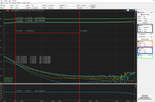
Probably this is the most important test, by far. I changed the 100k+100k loads with 52k+13k, a 4:1 ratio, I still have about 19-20Vrms between phases for 1Vpk input, 6DJ8/6N23P .
Please, show me a classic inverter with 2-3 triodes which does this without GNFB!
Please, show me a classic inverter with 2-3 triodes which does this without GNFB!
Attachments
Last edited:
Truely amazing the 6DQ8 could take that kind of beating considering especially the max voltage ratings.
Just as 6a3summer, who allready asked for it, back in #7 i sure would have liked to see some pictures of squarewaves.
Dorin, would be great if you could post some, thanks
Just as 6a3summer, who allready asked for it, back in #7 i sure would have liked to see some pictures of squarewaves.
Dorin, would be great if you could post some, thanks
Last edited:
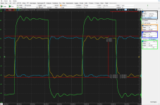
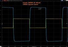
Here's input voltage 2Vrms into circuit, Bode up to 100kHz and 10kHz sqw, I provide these 2 measurements together, as a pack, for those willing to complain how bad the sqw looks ") ... no GNFB, yes?
... no GNFB, yes?
... the green line also shows how this xfmr behaves in SE.
But as I said I've tried the concept with bigger xfmrs which behaved also much better with sqw...
... no GNFB, yes?... the green line also shows how this xfmr behaves in SE.
But as I said I've tried the concept with bigger xfmrs which behaved also much better with sqw...
Attachments
Last edited:
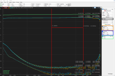
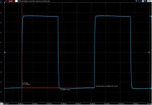
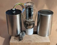
... just so that it does not remain a statement not covered by facts, here's one of the previous xfmrs, about 0.9kg each works wonderfully SE or PP or in Iron Schmitt circuit.
works wonderfully SE or PP or in Iron Schmitt circuit.Attachments
Dorin Bodea,
Thanks!
Your Post # 66 shows "ringing" at about 100kHz.
Only a fast rise square wave generator can make that show up on the square wave coming out of an interstage transformer.
No global negative feedback, so do not worry about it.
Some readers will disagree.
Red book CDs do not put out anything above 22.05kHz (other than bad CD players that have ultrasonic spurs).
With nothing above 22.05kHz, and CD player rise time limited by the 44.1 sample rate that is filtered at Nyquist (22.05kHz), there is nothing to activate the 100kHz "ringing".
Even Shibata LP records, and Shibata Phono Cartridges, will Not cause "ringing" at 100kHz.
Then there is the considerations of your ears and my ear that do not work at 100kHz;
not to mention that your tweeter, and my tweeter do not work at 100kHz.
Happy Listening!
Happy Sleeping after the listening session that goes far into the night.
@6A3sUMMER - exactly, one will need a very fast sqw generator to activate that "ringing", which above 100kHz has only downward tendancy anyway
... and nonetheless this is not a finished and polished circuit/product, as I said...
... and nonetheless this is not a finished and polished circuit/product, as I said...
Testing 'above and beyond' what the amplifier will ever be used for, or have to ever do (except for a critical magazine reviewer) are exactly that . . .
'above and beyond'.
I believe that some product reviews have destroyed sales of some good amplifiers.
After the bench testing, I highly recommend a listening test.
"What me Worry?"
'above and beyond'.
I believe that some product reviews have destroyed sales of some good amplifiers.
After the bench testing, I highly recommend a listening test.
"What me Worry?"
With only triodes in the chain, and without multistage fb, transformer coupled has certainly some advantages over capacitive coupling.
Alone the fact that the "gridresistor" can be the low Rdc of the secondary winding is a big assurance against possible tube runaway with neg gridvoltage biasing.
This alone wins, at least, the "peace in mind" category...
Last edited:
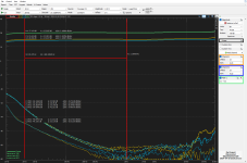
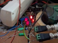
I thought it will be useful to complicate further the life of my phase inverter by loading it with a tough, composite load including LED diodes, asymetrical too (4k7+1k in series with LEDs)... in the first picture you have the simulation (with actual values too) and in the second picture the real life, measured at 1Vpk input... and yes, the LEDs lit beautifully
Later edit; the small diference between the simulation and measurement is because I used 6DJ8/6N23P, about the same amplification factor but dissimilar transconductance.


Later edit; the small diference between the simulation and measurement is because I used 6DJ8/6N23P, about the same amplification factor but dissimilar transconductance.
Last edited:
Dorin, thanks,Here's input voltage 2Vrms into circuit, Bode up to 100kHz and 10kHz sqw, I provide these 2 measurements together, as a pack, for those willing to complain how bad the sqw looks
... the green line also shows how this xfmr behaves in SE.
But as I said I've tried the concept with bigger xfmrs which behaved also much better with sqw...
the ringing frequency will get lower and amplitude will rise when driving the effective input capacitance of the output tube, or tubes, propable nothing to worry about.
You could get a closer picture of what it actual will look like, by loading with the equivalent capacitance of the tube you intend to drive.
Hi Dorin,
a 56pf cap should be pretty close (inclusive strays) to the equvalent input capacitance of a kt88 in quasitriode.
The nasties triode i know off, would be the 7242 with at least 3-4 times as much, but those are unobtainium monsters, so not very relevant.
More realistic would be two kt88 quasitriode in parallel, 2x56 or110-120pf caps
Last edited:
@gorgon53 - At post #62 we have a dissimilar load 52k+13k with measured response. For the sake of a gross exageration let's pretend the output impedance is 20k and the Miller capacitance is 200pF, then the upper -3dB cutoff frequency is still well above 35kHz - if we consider F=1/(2πRC) formula for a single-pole RC lowpass filter.
A single pole low pass filter that is -3dB @ 35kHz, and -45 degrees, is also . . .
-1dB @ 17.5kHz, and -26 degrees.
Use the phase inverter in a multi-stage amplifier.
Then consider the output transformer's high frequency bandwidth and phase lag at those frequencies
(mostly due to the primary to secondary leakage inductance, and distributed capacitance of the primary).
The high frequency response, and phase lag through all the stages of the amplifier is Cumulative.
Think about whether or not to apply global negative feedback from the output transformer secondary to 2 or 3 stages earlier.
Get it to work into a non-inductive resistor load.
Next, try connecting a loudspeaker.
@6A3sUMMER, there is no solution to everything.
Dorin is only showing what happens when basically things are done poorly. That's the worst case scenario. Otherwise the bandwidth is 100 KHz+ typically.....
Little point in using ITs with global fbk, IMHO. Normally, one would want to use them with linear devices, the more linear the better. The power stage can still be anything if use local fbk.
- Home
- Amplifiers
- Tubes / Valves
- Iron Schmitt phase inverter - lowest THD seen