@gorgon53 - I really appreciate your enthusiasm relative to this subject, but in the end I have a simple question for you (since you've failed to answer the previous); what is a "reactive load"? ") what do you think a 1:1 winding at, say, 10mA will look at the following grid?
what do you think a 1:1 winding at, say, 10mA will look at the following grid?
It's obvious for me that your experience with xfmrs was painfull, I understand, there is hope!
what do you think a 1:1 winding at, say, 10mA will look at the following grid?It's obvious for me that your experience with xfmrs was painfull, I understand, there is hope!
Looks like PP but is not, as you can see second harmonic is not cancelled. The first triode has partial anode and cathode load. The second triode is grounded grid connected, cathode driven. No cancelling of tube/load related h2 unless you drive both grids.
The transformer itself can only produce a second harmonic if dc magnetisated due to some imbalance.
The choke has dc magnesitation and therefore will add unavoidable h2 thqt will show up in the output and cannot be cancelled.
With both grid driven, there ideally would not be any current variation an therefore any choke induced distortion, but then again, you would not need any choke at all.
To improve this circuit, ditch the choke and use a balanced driver, a 50/50 split load triode or jfet will do (cant remember how its called in english)
You have good points, and I appreciate, but maybe you lack practice, I mean hands on xfmrs... also, the second triode can be more or less grounded... and here is a lot more to dig...
Last edited:
You forget you are looking at max output (i.e. max Pout of the amplifier as well). In practical use it's nothing like the sinusoid on the bench. In practical use, MAYBE (because most musical programs have precisely nothing at such low frequency) only happening on some peaks very sporadically and assuming that you use the full power. On top of this, considering your ability to hear 1% 2H at 20Hz at high SPL is basically zero and the IMD caused by it also small, it's just a technical argument with no practical consequences. IME, adding a concertina (50/50 split load triode or jeft) as you suggest is likely to make the overall performance worse as you are adding another active stage with its power supply with its 2 decoupling capacitors. If the choke is your concern, as technical exercise I would try a standard LTP with CCS in the tail loaded by the PP transformer but I don't think it will change anything.To improve this circuit, ditch the choke and use a balanced driver, a 50/50 split load triode or jfet will do (cant remember how its called in english)
Last edited:
Nope and I show you why your perspective is limited and you miss the point.You can look at it any way you want, but any triode will have lower distortion the smaller the relative.current load variation, period.
You have not realized that at 20Hz the 6n3p has to output 8 mA rms to deliver 50V rms into 70 H. Its quiescent current is just 7 mA and so it's not class A anymore. That higher distortion might just be the consequence of some small degree of unbalance caused by this. By comparison, at 50Hz where THD has dropped already to a small fraction of that at 20Hz, the output current has also dropped to 3.2 mA rms....
Use a 6H30 running at 15 mA and see what you get. As I said you don't need to swing full current in a driver stage like an output stage. Just use enough to stay in a linear working range.
I am not saying I am right because I have never tried this circuit but I would first investigate before jumping to conclusions like "ditch the choke"....
Last edited:
Looks like PP but is not, as you can see second harmonic is not cancelled
This proves that you don't understand what we are talking about here, you also failed to answer 2 simple questions, you are grounded to a dark corner for the next 3 (30?) days!
I have said!
Last edited:
On first post image and on schematics.
In my first post there is one schematic where the single transformer IT26PP is marked with a dotted blue line. It looks like attached picture, same shielding as for the initial IT26, a transformer developed initially for the triode type 26 and alike, 6SN7 for examp[le
https://www.diyaudio.com/community/threads/26-pre-amp.151421/post-7213064
Last edited:
I spent some time and I installed a classic LTP with 6DJ8/6N23P, of course, with almost double voltage supply. I also made some brief optimization in my circuit. In all the following cases I've compared the response for the same input level, I put them two by two for an easier comparison. I'll start with a 1kHz FFT, both channels
Attachments
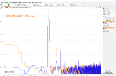
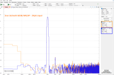

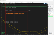
If it wasn't clear till now this is not a product presentation but a proof of concept, a simple idea with some merits. What's below say, 60-80Hz is, of course, core saturation of a very small and light xfmr (~280g) which has to deal with tents of Volts rms. In the past I've tested an xfmr about 3 times heavier (but still under 1kg) which coped with no sweat with more than 300Vpkk low frequency... so yes, size matters! ... maybe I'll construct a few pairs of the bigger one for comparison.
... maybe I'll construct a few pairs of the bigger one for comparison.What schematic had the classic LTP?
If it's classic is classic, 8 resistors and 4 capacitors... I won't waste time here but you can see in the first FFT that I rigurously equalized the 2 branches.
The Schmitt has definitely much better performance above 60Hz and it's still comparable below despite the limited size of your xfmr. I could live with that. So the proof of concept has worked. It's still unclear what is the influence of the inductance of the cathode choke on the balance (gain) between the 2 halves as the frequency decreases. In the original Schmitt the lower cathode resistor is of "large" value to get a good balance. In the Mullard variant only the lower cathode resistor remains and the coupling capacitor also disappears thanks to the DC coupling with the previous stage. In the classic application with the ECC83 such resistor is 82K (but it is mainly dictated by supply). With an ECC88 the minimum value could be lower but still some tens thousand ohms? Just trying to say that if the required L of the cathode choke needs to be at least 10x then using resistors like the original is more practical despite more voltage supply is required. It would be still be significantly less supply that all resistive Schmitt.If it wasn't clear till now this is not a product presentation but a proof of concept, a simple idea with some merits. What's below say, 60-80Hz is, of course, core saturation of a very small and light xfmr (~280g) which has to deal with tents of Volts rms. In the past I've tested an xfmr about 3 times heavier (but still under 1kg) which coped with no sweat with more than 300Vpkk low frequency... so yes, size matters!
Last edited:
In case you really do not know, the reactive load a transformer presents to the tube, or tubes, will consist of all the reactive components of the transformer itself, plus the transformed reactive components of the load the transformer feeds. At the low frequency end inductance, at the high end capacitance.@gorgon53 - I have a simple question for you (since you've failed to answer the previous); what is a "reactive load"?
It's obvious for me that your experience with xfmrs was painfull, I understand, there is hope!
Both L as well as C are reactive, in themself they produce phaseshift and demand, additional to the resistive loadpart, current from the driving tube.
The rest of your question is a bit unclear, but i will answer what i thinck you ment. The following grid is the driven part, without grid current it presents ideally only a capacitive reactive load that is depending on the driven tubes and theyr operation conditions. This appearend capacitiv load will appear, as i allready mentioned, transformed at the primaries, as part of the load that the phaseinverter sees.
Your case, 1:1 pp, with properly winding arrangement and properly wound (ideally bifilar) is about the easiest to get wide bw and tigth coupling beween primary and secundary. Primary : primary coupling less so. Is 10mA enough?
Most likely it is at enough at audio frequencies, unless you are driving some bank of high mu paralled triodes. as long as your inverter stays in a sensible class A operation range and the the transformer is wound properly. Your measurements look very good, so i guess it is enough. If i remember correctly, it was 45 who said at 7mA operation shifts into class B, if thats so, he also proposed the correct cure. I have no idea on what 45 based his conclusion, as i did see only a 1:1 pp transformer without any other info than 100k resistive loading, or did i miss something?
As to your "its obvious...." i very much suspects that you came to your conclusion because you are a comparable younger guy, that overconfident still climbs the mountain...
Some day you will hopefully reach the top, slide down the other side and reach the valley, till then, all the best on your way to get the over 60years of the vast varyity of expiriences i have, especially regarding transformers.
And, yes, i have not much expirience in WINDING audio transformers, other than a few in my youth when winding your own transformers was still a natural part of DIY.
Now, its over 4am here, i just glanzed through the thread to see what happend after the last time i was here. Some attitudes towards what i wrote, whilst trying to be helpful, pissed me off a bit.
Despite of that, i need some sleep now, am over 76...
Last edited:
@gorgon53 you write about reactive loads but then it's unclear how to assess if it works in class A or B? If you know the load you know the current the tube needs to provide for a given output voltage. It's quite simple relationship at low frequency because the only relevant load parameter is the primary inductance.
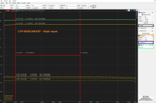
Before moving to (slightly) larger core let's see what this small xfmr does with 1Vpk~0.7Vrms input voltage, which results in about 11Vrms output on each phase or 22Vrms between phases (with 6DJ8/6N23P)... is this voltage usable for a (more than) decent PP amp? ... or I'm missing something important here?
Later edit; I think I started this presentation wrong by directly showing the extremes instead of presenting the normal situations in real life...
Later edit; I think I started this presentation wrong by directly showing the extremes instead of presenting the normal situations in real life...
Attachments
Last edited:
How to acess is it working in A or B ? It is class B the moment one tube gets cut off. The easely, do to unsufficient coupling of primary halfes produced voltage spike is one of the reasons why class B often sucks ( avoidable with unity coupled circlotron or mc intosh style bifilar wound).@gorgon53 you write about reactive loads but then it's unclear how to assess if it works in class A or B?
Resitive optimum secondary load current should be choosen by adjusting the optimum damping of the squarewave response with either a resistor, or a zobel.@gorgon53 If you know the load you know the current the tube needs to provide for a given output voltage.
At the high end, the capacitive load current, of the transformer itself, and of the following tube driven must be added.
At the low end, the inductive current of the transformer must be added.
High driving impedance of the transformer will give non peaking primary magnetisation current, but higher voltage distortion at the secondary
Low driving impedance givs more peaking magnetisation current and lower secondary VOLTAGE distortion.
All the above currents add up and must be provided by the driving tube at max voltage swing.
What i would like to know, given all those unknowns (concerning Dorins circuit), except for the max voltage level and the 100k resistors,
how did you come to the conclusion that 7mA would not be enough without entering class B ?
Last edited:
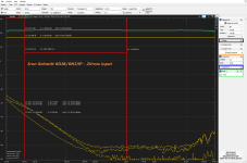
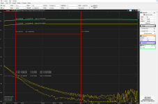
This circuit has a remarkable stability, what you'll see in the next 25 seconds is 2Vpk both channels input and a variation in voltage supply 25V-400V with 1mA-18mA per 6DJ8 triode, I know, I was affraid to go further
... when H2 dims into background noise the supply voltage is 310V with a current of 13mA per triode.
... when H2 dims into background noise the supply voltage is 310V with a current of 13mA per triode.
Attachments
Last edited:
- Home
- Amplifiers
- Tubes / Valves
- Iron Schmitt phase inverter - lowest THD seen