There is a problem - if only one "woofer" is used for upper mids (or a boost there) that one needs to be in close proximity to the tweeter otherwise it will be many wavelengths away from the tweeter and that may wreck havoc with anything resembling a good vertical dispersion pattern.
Indeed, this is a major consideration in the design, and may explain why Polk tried to keep the tweeter xover lower rather than higher...
Otoh the vertical dispersion pattern may not have been controlled in particular - by that I mean not without substantial lobes. It may be difficult to make this aspect of the speaker design "work" no matter what you do.
The big impedance rise in the xover region is a cause for concern. It should not be there, imo. I'd simulate the xover in SPICE and see what it looks like and/or actually measure the impedance - again with and without the tweeter and see how and why the impedance rises, since that is somewhat unusual especially in a series xover... it says to me that there is an error in the xover design wherein there is in essence a "notch" filter that looks like a high impedance at the input side formed by some combination of elements in the xover...
Just speculating of course...
_-_-bear
Here's what the FRD looks like -
Frequency(Hz) Magn(dB) D2(dB) D3(dB) D4(dB)
23.893 -58.85 -10.58 5.32 5.00
24.123 -58.84 -10.41 5.41 5.30
24.356 -58.82 -10.22 5.48 5.67
24.590 -58.80 -10.02 5.54 6.11
24.827 -58.77 -9.81 5.58 6.60
25.066 -58.74 -9.58 5.61 7.14
The first two columns are Hz and db and the rest distortion db. I dont see phase degrees.
I used to be a programmer. In order for any software to be able to read the FRD file, the file must follow a protocol. As far as I remember the third column is for the phase. You cannot change that by giving certain header on top of the column. And this is what the SW did. SW interpreted the third column as phase.
Your phase is indeed very awful. But it is common if you do it by measurement. Mic issues, reflection, sound card issues etc will produce bad looking chart. But it does look like a phase information.
Look carefully at the attached picture. The grey line is the phase information from the third column of your FRD file as read by SW. The yellow line is the H2 of your measurement.
Attachments
I did not modify the file in any way. ARTA produced it that way and the third column is really 2nd order harmonic. If you see further down in the file that column even stops recording (reaches upper limit of measurement sampling rate for second order distortion).
Come to think of it ARTA (free version) doesn't show phase in the charts as well.
I understand why SW interpreted that as phase, but it is not phase. I think I will need to redo the measurements in SW or HolmImpulse. Or I need to learn about ARTA a bit more.
Come to think of it ARTA (free version) doesn't show phase in the charts as well.
I understand why SW interpreted that as phase, but it is not phase. I think I will need to redo the measurements in SW or HolmImpulse. Or I need to learn about ARTA a bit more.
apparently ARTA does phase only in dual channel measurements.
..as phase is a relative thing. It would be wise to do woofer and tweeter measurements in the same session without moving the mic.
ok, here are the new frd files with minimal phase. In ARTA it was just a matter of selecting 'Minimal Phase' from the menu after recording the impulse, to get minimal phase. Measurements were done with mic and drivers fixed for measurements of both drivers. The drivers were mounted on the actual speaker baffle for the measurements.
These files are ready to plug and play in your favorite crossover design application.
and now I am off to climb the SW crossover design ladder...but would be nice to compare/check my work against yours, fwiw it would be a learning experience for me. Thanks much!
These files are ready to plug and play in your favorite crossover design application.
and now I am off to climb the SW crossover design ladder...but would be nice to compare/check my work against yours, fwiw it would be a learning experience for me. Thanks much!
Attachments
Did you use minimal phase on each of these measurements individually? If so, you have a problem. What you are needing to achieve is the phase difference between the drivers.
When you measure from a distance, the higher frequencies will have gone through several cycles before they reach the mic. This is OK except it's difficult to read the plot when it wraps around so many times so we usually eliminate some of the delay by subtracting the time it took for the sound to reach the mic, like you have done, making the plots easier to read.
What concerns me (although I am not familiar with how ARTA does this), is the the woofer and tweeter measurements need the exact same delay removed from each other. If you use some program to remove the excess delay from each plot, there will probably be a different amount removed from each which is the same as moving the mic between measurements.
When I do this kind of measurement I will do one of the drivers and manually select an amount of delay that unwraps the plot well enough for my liking. I will then do the other measurement and apply that same amount of delay removal, and accept the plot whatever it looks like. (for what it's worth, of course, if I don't like the looks of the plots I can do the other driver first)
If you'd confirm the phase in the frd files is good, I'll have a go as well and post the results if you'd like.but would be nice to compare/check my work against yours, fwiw it would be a learning experience for me. Thanks much!
What I did was select Minimal Phase option for each driver's measurement. Is that not the correct way of doing it ? Basically you record the impulse then select freq response analysis which shows the frequency response alongwith the excess phase and there you just select minimal phase option in the menu which results into the phase that is in the files I posted.Did you use minimal phase on each of these measurements individually?
I didn't follow, can you point to a couple of examples in those charts where it exhibits this behaviour ?What concerns me (although I am not familiar with how ARTA does this), is the the woofer and tweeter measurements need the exact same delay removed from each other.
What simply happens when you remove the excess phase, is that a certain delay, or time, or distance (all are the same thing) is removed. This will not alter the relative phase and the plot is still valid. When you think about it, this is the only acceptable adjustment to make.
For example, if we remove one millisecond of delay, we are showing what it would look like if our mic was 13.5 inches closer. This relates to 90 degrees at 250Hz, 180 degrees at 500Hz and 360 degrees at 1000Hz etc.
If you don't remove the same amount from each driver, it will be like moving the mic between measurements. It would be like putting the drivers in separate baffles and pushing one further back than the other.
Unless you control the amount of delay removal, I would be concerned that ARTA might try to be too helpful and remove as much delay as it can before it notices the plot wrapping the other way.
Changing the relative distances of the drivers (virtually or for real) will change the relative phase between them. Since relative phase is an indicator of whether the drivers are moving in and out in synch with each other, changing the phase of just one of them will change the relative phase between them.
Did you save the impulses?
If you are saying that the start marker of the gate should have been positioned right before the start of the impulse for both the drivers then yes that's what I have done. However, I did notice that whether I gate the measurement or not, i.e. regardless of the position of the start marker, there wasn't any noticeable difference in the final(minimal) phase response of both the drivers. Meaning the difference in delay really wasn't that much ?
No I did not or rather could not save the impulses (free version).
No I did not or rather could not save the impulses (free version).
Last edited:
No, not exactly what I meant. May be worth just using the phase information raw. I use a different program which has manual delay correction.
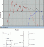
Anyway, I was playing with the files you gave. The image below shows a basic parallel crossover. The woofer components give the identical response to the series crossover you posted earlier. The only difference is that all three are contributing equally. Not sure whether something like this would sound better, it would be something you'd have to trial.
Anyway, I was playing with the files you gave. The image below shows a basic parallel crossover. The woofer components give the identical response to the series crossover you posted earlier. The only difference is that all three are contributing equally. Not sure whether something like this would sound better, it would be something you'd have to trial.
Attachments
Anyone want to comment on why the original manufacturer would have possibly designed the crossover the way they did ? Mainly why the 3 drivers are split and their responses shaped and staggered the way they are ?
Why not just all 3 woofers in series as one whole set of drivers like Jay’s and Allen’s first suggestions ?
Could it be just ease of manufacturing and pricing of components ? So they can reuse most of the parts and crossover design so its easy to slap on another diver as they go up each model in the line ? (M50=2 woofers, M60=3 woofers, M70=4 woofers). Or could there be any real technical reason for better acoustic performance ?
I've been thinking this could have been a creative way to approach the floor/ceiling bounce issue. You haven't posted the tweeter crossover that I've noticed, but you could redesign just that one and leave the woofers for the time being, although I did notice an improvement in the woofer's contribution with a notch filter.
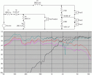
The tweeter is a 2nd order high pass. L=.25mh, C=8uf and a R=0.5ohm BEFORE the XO (i.e. not on the driver side of the xo). Now the 8uf electrolytic is bypassed by what seems to be a small film cap of 0.22uf (I am sort of assuming the value here as I can only barely read the numbers that appear to be "224J".
If I was to set a "goal" for this redesign initiative then it would be - moving the tweeter crossover point further up as I hear audible distortion between 1.5khz to about 4khz. Thats the biggest flaw of this speaker as I see(hear!) it.
And if the crossover point of the tweeter was moved up then I would imagine that would call for adjustments to the woofer/lowpass crossover as well. Sure I can keep the stock configuration of the lowpass section and just optimise the component values to bridge the gap but I would just like to explore other possibilities, or atleast their feasibility.
Anyone want to comment on why the original manufacturer would have possibly designed the crossover the way they did ? Mainly why the 3 drivers are split and their responses shaped and staggered the way they are ?
Why not just all 3 woofers in series as one whole set of drivers like Jay’s and Allen’s first suggestions ?
Could it be just ease of manufacturing and pricing of components ? So they can reuse most of the parts and crossover design so its easy to slap on another diver as they go up each model in the line ? (M50=2 woofers, M60=3 woofers, M70=4 woofers). Or could there be any real technical reason for better acoustic performance ?
Well, the answers to that would be self evident with a bit more measurement and testing.
I'll speculate.
 <-- "2 cents worth"
A whole lot depends on the basic response of the woofers, their reference sensitivity AND their impedance. Then the next issue is the response in the actual cabinet size. Add in the T/S parameters.
Now we've got a speaker design balancing act that we'd have a reasonable amount of information about in order to make some basic design choices...
My guess is that the woofers are "cheap" compared to a bigger box (which is bad from a marketing standpoint) and that Polk wanted as much output as he could muster and that three speakers sell better than 2.
A good look at the stock freq response curve, the real one properly measured, would reveal more of the design compromises that were picked.
Beyond that your guess is as good as mine... (obviously, the "third" woofer provided some "EQ", based on the xover info posted earlier...iirc)
_-_-bear
If you did post the tweeter crossover (either a diagram or a photo) we could sim and analyse the current response to find an adjustment that doesn't change the balance too much.as I hear audible distortion between 1.5khz to about 4khz. Thats the biggest flaw of this speaker as I see(hear!) it.
Maybe/maybe not. The most likely tweak would be to adjust the inductor, which may not upset the original woofer distribution.And if the crossover point of the tweeter was moved up then I would imagine that would call for adjustments to the woofer/lowpass crossover as well.
I think this is all worth a try.
Anyone want to comment on why the original manufacturer would have possibly designed the crossover the way they did ? Mainly why the 3 drivers are split and their responses shaped and staggered the way they are ?
Why not just all 3 woofers in series as one whole set of drivers like Jay’s and Allen’s first suggestions ?
There is no rule on what shape/arrangement to choose. It is all based on the drivers used. It should sound good, and measure good. To sound good, you have to choose arrangement based on listening. To measure good, it depends on the drivers' parameters, but usually doesn't limit arrangement possibility.
I have never listened a series of 3 woofers in a 2-way filter. I don't know how well the blend (between woofers and tweeter) will be. It cannot be predicted. It could be just fine. In other words, for any specific design, it must be listened to.
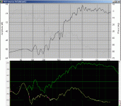
I don't know about Polk. I cannot assume that they are doing their best. The peak on the tweeter shows that like many other speaker manufacturers they didn't do their best.
What filter to recommend depends on your way of design. Here I have plenty of coils with varying values. This kind of "design tool" is not expensive when you do design expensive speakers. I always build and compare several filter and choose based on listening.
If you want to buy only one set of filter component and tweak based on the small number of components (and whether you own an L-meter), I may be able to suggest which design to build.
The series crossover will be the easiest way to tweak. It works with many possible component values.
The simplest crossover is parallel second order. Simpler usually sound better (If the subjective performance/measurement is acceptable). If your original crossover works just fine (the series filter on woofers), then I believe it would be fine also with parallel second order. The effect of blending/lobing you can judge by listening, but simple crossover do not have many problems.
I will build the simplest crossover soon, along with relative performance (response) to the original crossover.
I will build the simplest crossover soon, along with relative performance (response) to the original crossover.
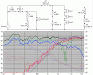
Here is the simulated original crossover. Deep null is at 2K3. As you can see and hear, there is a peak on tweeter response around 2K. This can be fixed using:
1) Notch filter
2) Sharper slope (third order filter)
3) Higher xo point (second order filter)
With the third option we must ensure that woofers will be just fine, which I predict they will.
Attachments
I will build the simplest crossover soon, along with relative performance (response) to the original crossover.
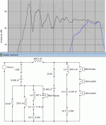
Here is a simple second order parallel (response charts are in bold) in comparison with the original (responses in thin lines). Deep null is at 3K2 (original at 2K3). What we can see here:
1) Tweeter response better addresses the 2K peak issue.
2) Each woofer is better attenuated than the top woofer of the original speaker (Peer3). Note that the thin light blue line is for the original Peer3, not Peer2/Peer1. You can confirm this from the values of components used in both filter.
3) Simulated phase overlap is good (2 octaves above and below xo point) as can be seen from the dotted lines (or the deep null).
4) Total response of the new filter have a slight dip at xo area, but this doesn't tell anything soundwise.
Attachments
- Status
- This old topic is closed. If you want to reopen this topic, contact a moderator using the "Report Post" button.
- Home
- Loudspeakers
- Multi-Way
- Inviting design ideas for these drivers and cabinet (files and pics inside)