David, you are absolutely right, the baffle is 250mm wide.
Guys, I would like to wish you a happy new year!
Happy New Year to you too!
Have been having a play with this, and while I can get a proper HPF in for the mid and still keep the overall impedance above 4Ω, I'm not convinced that what I've got is particularly great in a few other aspects.
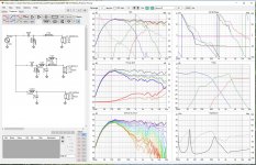
Couple of notes first - VituixCad is what I'm more familiar with, and in order to have a look at off axis as well as on axis response I used its diffraction simulator, so my basic freq responses may be slightly different than yours.
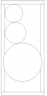
I assumed all drivers were horizontally centred on the baffle as that matched your raw curves the best, especially for the HF, but that does throw up a complication. Both the mid and HF acquire dips between 2k & 3kHz, which means getting a smooth crossover there seems to need pushing the XO up over 3kHz. That tends to result in a bit of a dip in the off axis responses at & just above the crossover. If you were able to make up a new baffle for your box with the mid & HF offset towards the side, that area smooths out a lot, potentially allowing a lower XO and smoother off axis response.
Other areas I'm not totally happy with are the phase between drivers (I haven't improved that over your version at all) and the use of some pretty hefty components in the low and mid filters, 75uF in the Low and 10mH in the mid are going to be expensive unfortunately.
Anyhoo, this seems to be the best I can do at my current skill level, sorry it's not better news.
Attachments

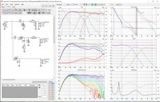
Couldn't resist playing with offset drivers a bit, I think the midrange is a lot smoother on axis, DI is a bit smoother from 1k to 10kHz (less narrowing at the mid-high crossover), and a few components have moved to more affordable values too.
Attachments
Sometimes you should use the BSC circuit, I'll show when and why. (2 posts)but seems not using extra BSC
Here, the baffle step (the blue trace) is around 500Hz . You are trying for a 2nd order crossover at 800Hz (the pink trace).
With the standard component values, the baffle response lifts the combined response too high. So I've increased the capacitor and inductor values to give the correct response.
To illustrate this, if not for the baffle step these chosen larger values would look like the red trace. If you combine the red with the blue, the result is the correct pink trace.
Now, look what happens when we try to use the same 2nd order type of filter, but this time the baffle step is at 500Hz and the crossover is at 2,800Hz. The crossover falls across the range of the baffle response and is kinked both up and back again.
Since the shape is wrong, the orange trace is the best you can get with this circuit. The more complex shape needs a more complex circuit.
Now, add the BSC circuit... Perfect.
Again, the red response shows what the filter looks like on its own before the baffle response imposes itself. The red trace has the opposite kinks in it and the final pink response is correct.
Now for a first order filter. Otherwise this is the same 500Hz baffle frequency and 800Hz cross.

The orange trace is the simple filter. It is not possible to get the response right above and below the knee of the rolloff (say, roughly 1kHz), at the same time. The extra two components help give exactly the wanted pink response.
The orange trace is the simple filter. It is not possible to get the response right above and below the knee of the rolloff (say, roughly 1kHz), at the same time. The extra two components help give exactly the wanted pink response.
Hi David,
Sorry I was away and missed your messages.
I really appreciate your calculations! I will study them more carefully on weekend.
I have been thinking and finally decided to try to build new speaker cabinets. As you mentioned above it has some benefits if we offset drivers and so on. I also like that you shift mid by 120mm and woofer(295mm) relatively to tweeter. I thought about that but was not sure if it has significant impact.
Hi Aniva, those vertical offset values simply reflect the positions of the drivers on the baffle, in real life they obviously can't all be at 0,0,0 as they can't all occupy the same space. In this case, all of the modelling was done with what I believe is VituixCAD's default "measurement" distance of 3m from speaker to the simulated mic position, so even the bass driver is only <6o off axis, so it won't make more than a few tenths of a dB difference to the overall modelled response.
No worries.
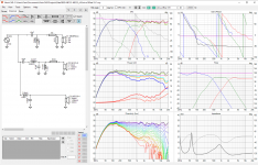
In VituixCAD, the depth is set with the Z axis, so as modelled that assumes all the actual diaphragm surfaces are aligned in a flat plane.
Practically, you'd need a stepped baffle a la Troels G to achieve that, as the woofer is deeper than the mid which is in turn deeper than the HF.
If built flat, that does worsen the phase behaviour a bit (Depths assumed, based on ~0.5x the depth of each cone, don't take this as gospel!):
Attachments
🟢 It was everything I was looking for, I will devote myself to reading it in full, occasionally I will trouble you with questions!CHOOSING THE CROSSOVER FREQUENCY - Part 1
You will firstly need to choose a crossover frequency that gets the best out of the drivers. If we choose too high a frequency, we risk poor sound from the woofer, and poor matching to the tweeter. If we choose too low a frequency we risk distortion and power handling issues with the tweeter.
Get some spec sheets
If you haven't already, collect the specifications for each of the drivers which you'll likely find at the manufacturers website. (if not, read on… but there'll be more on what to do at the end of this section.)
A spec sheet should show a bunch of numbers relating to things such as - how much power it can handle, how big is the cone and how far does it travel, how loud it plays compared to other speakers etc…
The spec sheet should also show a graph with a couple of lines plotted on it. One line will show how the speaker produces sound by plotting how loud the speaker will play at each frequency. The other will show how the speaker behaves electrically by plotting how it conducts electricity at each frequency.
Woofers - choosing where to cross
If you look at the woofer's frequency response plot shown below, you will see that the woofer has a peak in its response at 4kHz (4,000 Hertz) just before it rolls off above 7kHz. In other words, it will play too loud at these frequencies. This peak is not uncommon for a woofer but it will not always be obvious when looking at some plots.
It is the region of cone breakup, and it is the result of the cone flexing when working at these frequencies. Woofers don't normally sound good here and it is best to cross them over below this point which prevents them receiving as much energy at these frequencies.
A rule of thumb is to leave at least an octave (or two) between the crossover point and the cone breakup. An 'octave' means a doubling or a halving in frequency, so in the case of the woofer shown below, our crossover should probably be at or below 2kHz.
Hello AllenB, I am also going to attempt a 3way system. I have JBL woofer and and JBL full range 6.5 woofer as midrange and an LCY103 tweeter. Woofer is rated 96db, 16 Ohm, mid is 89db,also16 Ohm. Tweeter is 96db and 4 Ohm.
I had read sometime back that there may be a 4db gain in the midrange when a woofer's bass energy is rolled off above 80Hz. If this is the case wouldn't it present an easier leveling overall? Could I not bother matching the output of tweeter and woofer to match the 89db of midrange?
I had read sometime back that there may be a 4db gain in the midrange when a woofer's bass energy is rolled off above 80Hz. If this is the case wouldn't it present an easier leveling overall? Could I not bother matching the output of tweeter and woofer to match the 89db of midrange?
The 80Hz/4db is a function of gain, or perhaps I am not comprehending what I am reading.Before you sort the level of the tweeter it might be best to see what the others come to.
About the 80Hz/4dB thing, do you have a link to where you read this or can you give me an example? Usually the baffle step is not changing much at that low a frequency.
"Dr. Bullock's second order APC (linkwitz-Riley), three-way crossover formulas." Page 84, speaker building 201 Ray Alden. I apologize if I am directing my question in the wrong context, but this gain issue has me perplexed. The Math in this book begs for measurements but I am lacking the proper gear to do so. This is why I posted here and hoped you could clarify.
Still in the planning stages so, I'll keep this in mind when I build the boxes and tackle the Xover. Another question both woofer and midrange rated at 16 Ohms, they should be easy load to drive?A 96dB woofer will normally be close to an 89dB mid if you leave their levels alone and cross around the baffle step. This leaves you to look at bringing the tweeter down to the mid.
I don't have the book you mention. If you are avoiding posting it due to copyright reasons, you can private message me the relevant part and I'll try to explain it.
As far as 16 ohms, you probably don't need to do anything... To some degree your amplifier will need to have sufficient voltage to drive them. In other words compared to 8 ohms it draws less current but requires more voltage. To put it simply, you'll want an amp capable of high enough power but it won't be getting hot, relatively speaking.
As far as 16 ohms, you probably don't need to do anything... To some degree your amplifier will need to have sufficient voltage to drive them. In other words compared to 8 ohms it draws less current but requires more voltage. To put it simply, you'll want an amp capable of high enough power but it won't be getting hot, relatively speaking.
Ok AllenB, I will look into quoting the text from this book. I also have questions on how a capacitor will cause what it does to a woofer in parralel as in a cap. in the 2nd or 3rd order position and why it does what it does. I am away from my home till late monday evening. I'll gather the text and send at my return.
When a component is across the woofer like that, it partially short-circuits it. Some of the current flows through the component instead of the woofer.
Another way of looking at it is that if you combine the capacitor and woofer electrically, they look like a lower resistance. This means they see less voltage.. more will be dropped over the series inductor instead.
Also note that since you were talking about a capacitor, this means the partial short circuit is more effective at higher frequencies.
- Home
- Loudspeakers
- Multi-Way
- Introduction to designing crossovers without measurement