for sure. I didn't write about boundary interference though, only about driver on the back and could the back driver make some sort of "counter bafflestep", compensate for bafflestep. I don't see good bafflestep compensation without delay or having the dip.
The bafflestep appears because more sound goes around the baffle, less interaction with the baffle and enclosure as wavelenght gets longer. From back woofer the sound comes around to frontside and interacts with the sound from front woofer, which causes interference depending on wavelenght and direction and hence dip on the front axial response (and back since it is symmetric situation without filters). There would be corresponding boost to some angle, possibly at 90 degrees to side if power is flat. Where front to back distance is less than say 1/4wl constructive interference would happen to all directions and bafflestep would be compensated.
Bafflestep happens at low frequencies, where wavelenght is long, as the whole baffle/enclosure gets small in comparison. There are effects on baffle shape, sides, back, surface features, but these tend to be a bit higher in frequency, above bafflestep, because they are smaller than the enclosure. For sure some features could be big and influence the response, but then the bafflesep would appear lower etc.
But you are right, my sim is not whole picture and could contain mistakes as well. Perhaps wide but shallow eclosure would show better results for such baffle step compensation system.
Last edited by a moderator:
I am surprised that no one has mentioned another bsc technique. Using a 2nd driver at the back of the cabinet
If i have not already, that is in the old article i wrote as an intro to Jason Neal’s BSC article.
http://www.t-linespeakers.org/tech/bafflestep/intro-bds.html
dave
the "reverse bafflestep"
Not a good analogy given the affect. In 2012 the issue was named the bipole dip. One gets the same affect with a loudspeaker of finite thickness sitting on a wall.
It can be minimized by increasing the width to depth ratio, or mostly eliminated with a LP filter on the second driver.
We have also explored mounting the second woofer on the side or top, which can do much the same thing baffle-step wize.
It should be noted that if one looks at the driver front/back such that they are on the sides, there is no bafflestep dip as the 2 drivers perfectly blend. This can be used in a woofer situation (up to a certain frequency) where the woofers are XOed sufficiently low enuff. With a pair of 5.25” we did 450 Hz for example. This also brings the advantage of push-push woofers which dramatically reduces the box vibration load due to the active reactive force cancelation.
dave
Last edited:
Hi dave,It can be minimized by increasing the width to depth ratio, or mostly eliminated with a LP filter on the second driver.
can't get the dip eliminated with low pass filter on the back driver, the dip only moves around as the filter causes more delay. I'm thinking and experimenting this without the ( front ) wall, anechoic. Lets think it through: If considering single driver on front of the speaker, and wall behind, it is kind of similar thing as you say. There would be secondary sound towards listener, reflection from the wall, which would cause interference with the direct sound and a dip (series of dips and peaks) in the response would happen. Difference is, from the listener point of view, the sound travels twice the distance in comparison to a speaker with additional driver on the back in anechoic, no wall, situation. Sound travels from front to wall, reflects and travels back to front, and continues towards listener. In case of additional driver on the back, but no wall to cause reflection, Sound from back driver would just go from back to front, twice shorter distance than the previous case, if the wall was same distance away as the back driver. The resulting interference on front of the speaker would be similar but octave higher in frequency since the path length difference of the secondary sound was twice as long.
Perhaps you guys are considering there is both front wall and the back driver? In which case the back driver could be used to counteract the sound from front driver towards wall, a cardioid system. This would address the bipolar dip mentioned. This would be nice but it would not compensate the baffle step as per the topic. With cardioid there would still be need to compensate the "lost" low frequencies, compensate missing low frequencies.
Actually the low frequencies are not lost or missing, it just radiates elsewhere than directly to front, which looks like baffle step in the on-axis response. Sound will propagate to all direction and the baffle makes the high frequencies mostly towards front, towards listener. The baffle step is "problem" on the front of the speaker, from the listener perspective. On the back we have reverse situation, lack of highs!
Well, one more experiment if secondary driver somewhere would compensate for the baffle step, equalize low and high frequencies towards the listening spot. Here is a test with very ideal situation, without caring physical dimension
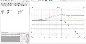
Notice the power if flat (blue trace), only the axial response towards listening position drops (green trace) and our plan is to boost that, sound towards listening spot.
There would be roughly two ways to achieve this, either project the lows towards the front by enlarging the baffle or boost the power on the lows / reduce power on the highs. Boosting the power could be done by adding low passed driver as dave and perhaps others ment, or by EQ with the single driver. Wider baffle would keep the power constant since we are not adding power to the system, just widening the baffle, projecting lower frequencies towards listening position. Boosting the power would not affect acoustics, and boost the lows to all directions, including towards the listener.
Ignoring the walls for a minute, lets add another driver at exactly same spot but rotated around (not possible with physical objects):
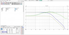
Nice! Axial response perfectly flat, power as well! Dashed lines are the single driver response as overlay to illustrate we actually boosted the power, lows towards listener were boosted and did nothing to highs towards listening spot because they radiate to the back. Problem is we cannot do this in reality. Lets add some depth to the system, distance between front and back to accommodate the driver frames and sheet stock.
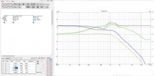
Now we have interference happening because the situation is not a ideal point flat disk anymore. Losing power..
What if the back driver was just on the front?
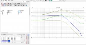
Nice! Even better, we have more power (ideal situation both sources exactly aligned) than with any of the previous examples. Lows towards listening situation were boosted, but so was the highs and we are back to square one, the sound is not equalized.
What do we learn? Many things
1. In most ideal situation that can never happen with physical objects we could compensate for baffle step with read driver. But, as soon as any dimension was introduced interference happens on the higher end of the baffle step bandwidth at least with narrow baffle. With a low pass filter (from previous experiment) this interference just moves lower in frequency.
2. With passive / active EQ we could equalize the power without introducing interference to the system, hence it would yield better results and would be cheaper than additional driver.
3. If additional driver was used, the front is better place for it than the back because there is more power to waste in the EQ and no interference (except vertical, which could be an advantage).
What we did not learn: what if the baffle was wide, a lot wider than deep, would back driver help then? Or, with any baffle would the back driver help with bounce from the front wall and how?
Alright, lets do 1m wide baffle. It is the same 8" ideal driver on the middle.
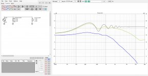
Now the edge diffraction makes a huge problem and we should use roundovers, which would reduce the apparent bafflestep as well (reduces diffraction hump. And, now we are on the ~100Hz region where baffle step wouldn't perhaps bother due to room taking over the response. It is interesting that now there is hump in the power as well, and the bafflestep is total almost 8db! A phenomenon I don't know about.
Anyway, lets checkout what if there was the same coincident source backside, like in the previous example (physically not possible):
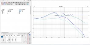
Again the one driver start situation is as overlay, dashed lines. Yeah, the response is perfect, equalized to flat and even the diffraction is gone like with narrow baffle. Unfortunately this is not physically possible..
What if we add depth to "the box", 15cm like with previous experiment:
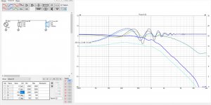
The bafflestep is partially compensated but the diffraction is still there, basically things just moved up in frequency.
How about low pass on the back driver?
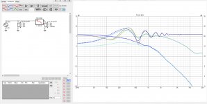
Nah, it just adds delay to it and makes things even worse, further from ideal situation which was physically impossible. If filter was moved up the delay gets less but doesn't disappear. Until there is no use from the low pass. I don't see how it would be usefull? other than kill the highs radiating back, but doesn't help with the baffle step at all.
Ok what we learned from here?
Perhaps round, wide enclosure would work, wouldn't have the diffraction, reduced baffle step due to no diffraction hump adding to it? But in this case perhaps there is no need for baffle step compensation at all.
We also learned there is a lot more diffraction related interference in addition to the baffle step, with the wide baffle. We could put the speaker in wall to remove the baffle step and diffraction altogether. Can't get bigger than wall to fit in the room.

Now the edge diffraction makes a huge problem and we should use roundovers, which would reduce the apparent bafflestep as well (reduces diffraction hump. And, now we are on the ~100Hz region where baffle step wouldn't perhaps bother due to room taking over the response. It is interesting that now there is hump in the power as well, and the bafflestep is total almost 8db! A phenomenon I don't know about.
Anyway, lets checkout what if there was the same coincident source backside, like in the previous example (physically not possible):

Again the one driver start situation is as overlay, dashed lines. Yeah, the response is perfect, equalized to flat and even the diffraction is gone like with narrow baffle. Unfortunately this is not physically possible..
What if we add depth to "the box", 15cm like with previous experiment:

The bafflestep is partially compensated but the diffraction is still there, basically things just moved up in frequency.
How about low pass on the back driver?

Nah, it just adds delay to it and makes things even worse, further from ideal situation which was physically impossible. If filter was moved up the delay gets less but doesn't disappear. Until there is no use from the low pass. I don't see how it would be usefull? other than kill the highs radiating back, but doesn't help with the baffle step at all.
Ok what we learned from here?
Perhaps round, wide enclosure would work, wouldn't have the diffraction, reduced baffle step due to no diffraction hump adding to it? But in this case perhaps there is no need for baffle step compensation at all.
We also learned there is a lot more diffraction related interference in addition to the baffle step, with the wide baffle. We could put the speaker in wall to remove the baffle step and diffraction altogether. Can't get bigger than wall to fit in the room.
I'm using the full 360 horizontal and vertical data from diffraction tool. The graphs on the previous two posts intentionally show only the Power & DI window with only axial and power response (light green is listening window), sound towards listening position. This is because the baffle step appears towards listening position only ( forward direction ). Just for purposes of this particular topic, testing if it could compensate low frequencies towards listening position that are "lost in baffle step".
The experiments took the suggested two driver approach as an example, if it would work as method for compensating baffle step, equalize sound towards listening position. It kind of works with shallow enclosure, and without any filters. But, this would project high frequencies to back as well, or low pass could be used which makes the dip appear (worse). So, considering only compensation for bafflestep = equalizing sound towards listening position this is not good method, use another driver on the back. Better is to use EQ, no unintended side effects. If another driver was used, put it forwards instead of back.
The experiments took the suggested two driver approach as an example, if it would work as method for compensating baffle step, equalize sound towards listening position. It kind of works with shallow enclosure, and without any filters. But, this would project high frequencies to back as well, or low pass could be used which makes the dip appear (worse). So, considering only compensation for bafflestep = equalizing sound towards listening position this is not good method, use another driver on the back. Better is to use EQ, no unintended side effects. If another driver was used, put it forwards instead of back.
For sure there would be some difference with real world measurements, it just is very much work to do to get details that are not useful inspecting the big phenomenon, the baffle step, which is the long wavelengths. Details would be on higher frequencies and resolution would be low on low frequencies unless measuring anechoic facility. I'm not sure if there would be any difference for reasoning purposes? reasoning about the baffle step compensation from ideal case would rule out all the worse cases as well.
It is late and I'm just a hobbyist so there can be miss judgement and overlook on the experiments, although I'm pretty confident on it Doing it your self on the simulator is kind of revealing, the still screenshots don't contain most of it, the experience of the system interacts with the parameters.
Sure, if one wants the highs on the back as well, or some other stuff to happen than just compensate for baffle step, then another driver on the back might be good. If more pros than cons, why not.
ps.
Mo tests coming, figuring out how to add the wall to the simplified ideal scenario soup and I think I got it. Too late though to write it.
It is late and I'm just a hobbyist so there can be miss judgement and overlook on the experiments, although I'm pretty confident on it
Sure, if one wants the highs on the back as well, or some other stuff to happen than just compensate for baffle step, then another driver on the back might be good. If more pros than cons, why not.
ps.
Mo tests coming, figuring out how to add the wall to the simplified ideal scenario soup and I think I got it. Too late though to write it.
Nonsense. You're just using the wrong type of simulation.it just is very much work to do to get details that are not useful inspecting the big phenomenon,
Quickie trying to cancel effect of the wall with back driver. I've got third driver, which contains only the 180 deg response of the front driver representing reflection from the wall. This can now be positioned where the wall would be acoustically, in other words double distance behind the front driver like I explained earlier. Sound from front driver travels to the wall, then reflects back and travels the same distance again to reach the direct sound. Power response won't be right I guess, but the axial response should be about right assuming ideal reflection from the wall. Then fourth driver can be added to represent reflection of the back driver 
Here demonstrating "the wall" interacting with front driver. Looks the same as there was the back drivers response to back, I mean towards listener Until the distance is doubled

Now, bipolar back driver enabled at 15cm deep enclosure like in the previous examples. This is the narrow baffle by the way to reduce the diffraction ripple to clearly see the baffle step. Here the wall is 20cm behind the speaker, 20cm from the baffle perpendicular to the wall so that the reflection is ideal, straight through the speaker In real world there would be longer path length around the baffle, toe in, what not. All in all, mostly affects the long wavelegnths and making the path length difference between direct and reflected sound even longer, with some additional ripple. The important thing is the low frequencies which are not affected too much, because the enclosure is relatively small. Remember, this is the baffle step, long wavelengths go around the enclosure. We try to see if the lows rise to the highs.
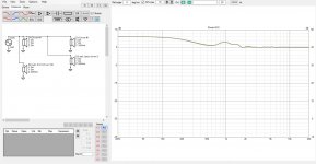
Nice! Power is hidden now, the "wall reflections" would make it calculate wrong. There is the front driver and its reflection with 40cm path length difference (as if wall was 20cm behind) as well as the bipolar driver, whose reflection path length difference is 5cm to wall + 20cm to front = 25cm. We got overcompensated! Some ripple on the response but not bad.
Here bit further out, 30cm out from the wall.
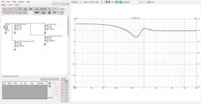
Oops, already dip from the wall bounce that we don't cancel. Things escalate quickly due to the double path length, reflection being behind the speaker and round trip happens towards listener.
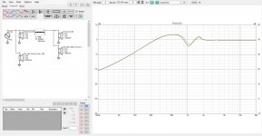
How about flipping polarity on the back driver? Dip is gone, but another appeared higher up and we lost the lows.
Further experiments, learnings and discussion tomorrow, gotta go sleepin
Here demonstrating "the wall" interacting with front driver. Looks the same as there was the back drivers response to back, I mean towards listener

Now, bipolar back driver enabled at 15cm deep enclosure like in the previous examples. This is the narrow baffle by the way to reduce the diffraction ripple to clearly see the baffle step. Here the wall is 20cm behind the speaker, 20cm from the baffle perpendicular to the wall so that the reflection is ideal, straight through the speaker

Nice! Power is hidden now, the "wall reflections" would make it calculate wrong. There is the front driver and its reflection with 40cm path length difference (as if wall was 20cm behind) as well as the bipolar driver, whose reflection path length difference is 5cm to wall + 20cm to front = 25cm. We got overcompensated! Some ripple on the response but not bad.
Here bit further out, 30cm out from the wall.

Oops, already dip from the wall bounce that we don't cancel. Things escalate quickly due to the double path length, reflection being behind the speaker and round trip happens towards listener.
How about flipping polarity on the back driver? Dip is gone, but another appeared higher up and we lost the lows.

Further experiments, learnings and discussion tomorrow, gotta go sleepin
Last edited:
There is the one filter shown in few of the attachments. Back driver is the right most, with positive Z value. Positive Z is further from the inspection point, the listener. A low pass on the back driver.tmuikku, where are you LP the rear woofer?
Also given that a wide baffle will push BS into the room dominated region, the small issues with bipole dip are swamped by the room.
dave
And exactly, wide baffle would not need baffle step compensation because the room would control the lows, wrote that already. Just trying to zoom into using second driver with the baffle step compensation in mind, where it would be useful and where not.
Last edited:
Could you expand on this? I'm inspecting only the axial response here, not what happens in the whole room. Compensating for baffle step in the sense of equalizing the axial response and it is irrelevant what happens outside of that in this case. If you count in the room then all bets are off even with the BEM stuff and in room measurements / listening would be needed. This is just to inspect how we could compensate for baffle step with another driver. You could sim it all and figure out the in-room estimate / response, surface materials and all, but would it come to conclusion that back driver is more useful compensating bafflestep than few components on crossover, or the same driver on front instead? I would not bet on this. Took few minutes to experiment this in the simulator + reasoning and few hours writing it out.Nonsense. You're just using the wrong type of simulation.
I know I leave a lot out from the text unintentionally, try to follow. Trying to output the relevant part and trusting the forum format would provoke some discussion on it. Criticism is good, thanks providing it, there aren't many
Check out the latest post which expands the experiment with simplified wall behind. Basically it is just summing up some impulses, whacked together using imagination. It is just a tool
Last edited:
@rhythmsandy,
Thanks for the answer. So the extra bsc coil + resistors given by The Edge sim.
I ask because I see very few extra standalone coil for the baffle step correction at looking most of designs, T Gravsen, etc.
My cabinet is a 28 cm baffle width and the 8" crossed at circa 450/500 hz seems not very easy without BSC...halas.
In his 3 ways classic, Gravsen cross over higher circa 800 hz but seems not using extra BSC... I wonder how the measurements are done or what the trick...? I chose the SB23NBAC and I do not think a XO at more than 500 he LR12 is feasible due to break ups... BS f3 is around 440 hz IIRC. I use the simple formula 11 900/width in cm to get the midle 3 dB atttenuation...
Last edited:
Good morning! HAh, and there is something wrong with the last experiment including "the wall", continued now after short night sleep on it and the top end was gone without filters, wtf  Whipping the setup up with proper driver names (front and back was same driver instance/copypaste) which hopefully reduces bugs. Now there is proper interference on high frequencies from the back speaker wall bounce! Didn't notice this in the evening something is wrong. This response doesn't represent reality either, the "wall bounce" is right through the speaker. Let see if that can be ignored and if the experiment is develops any further, basically we would need the low pass on the back driver in reality as well for the same reason, avoid highs bouncing back from near by surface, or get the bipolar speaker further out in the room like jimgriffin did in the thread Stal linked to on post #59
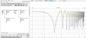
While setting up the simulation noticed something interesting with the back driver and its wall reflection when close to wall, well known stuff for many perhaps When very close to wall the situation roughly corresponds to the physically not possible situation I mentioned on the previous examples where front and back transducer being coincident the baffle step and diffraction seemed to sum to a flat response. And here it is, the back driver very close to wall. "direct sound" towards listener is low frequencies that diffract around the enclosure, the stuff we "lose" on bafflestep, containing the "lost lows" and the wall reflects the sound projected forward from the driver with almost no delay (close enough to wall) containing inverse of this "baffle step" and they sum to flat towards listening position
Here are responses towards listening postion: "direct sound from back driver", Ideal wall reflection of back driver, both combined right up the wall (impossible) and pulled about 1" from the wall.
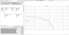
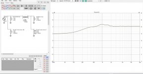
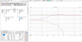
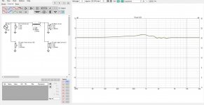
Except, in real situation we would have higher frequencies diffract and reflect between the wall and the speaker and what not and the result wouldn't be so nice, there is cavity between the driver and wall and what not. But, for low frequencies only this would work nicely. See, if back driver can be used up to ~1kHz in this ideal situation, 20cm wide baffle. Not much of baffle step! But, this is back driver only and ideal situation, but seems reasonable. For low (enough) frequencies this would represent as if the transducer was in wall as long as the speaker "obstructing" the sound is small enough in comparison not to cause, acoustically small. The pink line represents the direct sound if the driver was on a baffle.
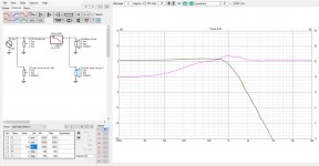
Now here BEM simulation of measurements would come into play, to see if there was speaker that would work so that the woofer was on the back and the next way on up on the front, mid and/or tweeter. The baffle width determines the crossover frequency, the usable bandwidth of both front and back driver. By usable I mean without signs of baffle step- It would be cool to investigate what kind of problems would arise from this kind of arrangement.
Here is quickie, low pass on the ideal back driver and high pass on the front: similar 8" driver on both sides like all examples thus far. Quick LR4 in order not to need to flip the phase
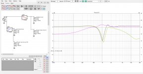
Uh, some interaction happening because the front is 15cm closer to listener. Not sure how to proceed from here, I'll fiddle around later and post if something relevant comes up. Mainly, if the box depth could be utilized with crossover filter in order not having to use separate baffle step compensation circuit Well, perhaps try what happens if the driver was on the front like most speakers have, 15cm is not too far from the wall
  Lets see later

While setting up the simulation noticed something interesting with the back driver and its wall reflection when close to wall, well known stuff for many perhaps
Here are responses towards listening postion: "direct sound from back driver", Ideal wall reflection of back driver, both combined right up the wall (impossible) and pulled about 1" from the wall.


Except, in real situation we would have higher frequencies diffract and reflect between the wall and the speaker and what not and the result wouldn't be so nice, there is cavity between the driver and wall and what not. But, for low frequencies only this would work nicely. See, if back driver can be used up to ~1kHz in this ideal situation, 20cm wide baffle. Not much of baffle step! But, this is back driver only and ideal situation, but seems reasonable. For low (enough) frequencies this would represent as if the transducer was in wall as long as the speaker "obstructing" the sound is small enough in comparison not to cause, acoustically small. The pink line represents the direct sound if the driver was on a baffle.

Now here BEM simulation of measurements would come into play, to see if there was speaker that would work so that the woofer was on the back and the next way on up on the front, mid and/or tweeter. The baffle width determines the crossover frequency, the usable bandwidth of both front and back driver. By usable I mean without signs of baffle step- It would be cool to investigate what kind of problems would arise from this kind of arrangement.
Here is quickie, low pass on the ideal back driver and high pass on the front: similar 8" driver on both sides like all examples thus far. Quick LR4 in order not to need to flip the phase

Uh, some interaction happening because the front is 15cm closer to listener. Not sure how to proceed from here, I'll fiddle around later and post if something relevant comes up. Mainly, if the box depth could be utilized with crossover filter in order not having to use separate baffle step compensation circuit
Alright, it looks like if woofer was on the back, enclosure right up close to wall and we could get rid of baffle step. And in addition, not much boundary interference either since the front driver projects forward mostly. There is some ripple due to edge diffraction but this could be perhaps reduced with roundovers / slants on the front. Exact details of diffraction all around real box up against wall are not available from this simple simulation.
Here is woofer on the back and mid woofer on the front trying to emulate more real system. The 15cm depth of enclosure works with crossover slopes, or the slopes are chosen to work with the delay due to depth, and result looks nice at least on axis. There is some ripple due to diffraction because it is small driver on relatively wide baffle with no roundovers.
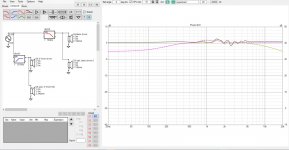
Here is situation if the woofer was on front instead. Bad boundary interference dip. Baffle step is compensated though
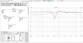
Basically what this is is a on-wall speaker, 20cm wide 15cm deep in this case. Woofer is on the back with 2.5cm gap between the box and wall, to get rid of the boundary interference dip and baffle step and then the smaller mid is on the front to reproduce higher frequencies towards listener. Crossover is somewhere around the "diffraction hump", roughly where the baffle step is on such baffle and there seems to be some leeway to adjust the xo point. The depth and width work together, width determines the xo point and depth related delay between woofer and higher way can be used in the crossover filters.
I have no idea how the response would be in real situation since this simulation doesn't take account the whole 3D space. I think main difference would be there around the diffraction hump/ baffle step start where wavelength interacts with the box on both front and back drivers. I don't know if the sound would be any better with woofer on the front or back as long as the box is right against the wall, both would show some interaction with the box and wall, (like any speaker in any physical size does, sound interacts with the environment).
Using both front and back woofer would introduce the interference dip, or baffle step (see previous experiments). If the speaker was further out in the room things would change, back driver would have distance to wall and cause the boundary interference dip just like front driver would. Basically, it looks like the back woofer would have to be close to the wall to be useful and box depth (front driver distance from wall) and baffle width and xo filters would play the game together how front driver integrates with the back driver. Mind you, box depth and width could be different with front and back drivers, but this would need to be measured/simmed in BEM to see what happens, interference would be even more chaotic.
As said here would be situation for measurements/ BEM to see if this would be something useful. All bets are off if the box was toed in or tilted up/down as the reflections would occur at different angle etc. But, the baffle step was compensated in this ideal scenario with no obvious downsides, towards listening position axis at least Basically the system approximates in wall speaker but being on wall. We got rid of boundary interference on low frequencies but didn't get benefit of reduced diffraction of a in-wall system. We got rid of the baffle step by effectively enlarging the baffle for the bass.
Here is woofer on the back and mid woofer on the front trying to emulate more real system. The 15cm depth of enclosure works with crossover slopes, or the slopes are chosen to work with the delay due to depth, and result looks nice at least on axis. There is some ripple due to diffraction because it is small driver on relatively wide baffle with no roundovers.

Here is situation if the woofer was on front instead. Bad boundary interference dip. Baffle step is compensated though

Basically what this is is a on-wall speaker, 20cm wide 15cm deep in this case. Woofer is on the back with 2.5cm gap between the box and wall, to get rid of the boundary interference dip and baffle step and then the smaller mid is on the front to reproduce higher frequencies towards listener. Crossover is somewhere around the "diffraction hump", roughly where the baffle step is on such baffle and there seems to be some leeway to adjust the xo point. The depth and width work together, width determines the xo point and depth related delay between woofer and higher way can be used in the crossover filters.
I have no idea how the response would be in real situation since this simulation doesn't take account the whole 3D space. I think main difference would be there around the diffraction hump/ baffle step start where wavelength interacts with the box on both front and back drivers. I don't know if the sound would be any better with woofer on the front or back as long as the box is right against the wall, both would show some interaction with the box and wall, (like any speaker in any physical size does, sound interacts with the environment).
Using both front and back woofer would introduce the interference dip, or baffle step (see previous experiments). If the speaker was further out in the room things would change, back driver would have distance to wall and cause the boundary interference dip just like front driver would. Basically, it looks like the back woofer would have to be close to the wall to be useful and box depth (front driver distance from wall) and baffle width and xo filters would play the game together how front driver integrates with the back driver. Mind you, box depth and width could be different with front and back drivers, but this would need to be measured/simmed in BEM to see what happens, interference would be even more chaotic.
As said here would be situation for measurements/ BEM to see if this would be something useful. All bets are off if the box was toed in or tilted up/down as the reflections would occur at different angle etc. But, the baffle step was compensated in this ideal scenario with no obvious downsides, towards listening position axis at least
Last edited:
I will show you that sometimes you can use the extra BSC circuit and sometimes you do not need it. First is an example with a baffle step around 500Hz, and you want a 2nd order crossover at 800Hz.but seems not using extra BSC
You can see the baffle step in blue. Pink is the response I wanted and I used the filter shown (it looks just like any 2nd order filter but the values are adjusted to work with the baffle step). Red shows the filter on its own without the baffle step.
Now, look what happens when we try to use the same 2nd order type of filter, but this time the baffle step is at 500Hz and the crossover is at 2,800Hz.
I cannot get the orange driver response to line up with the wanted pink response. The filter is too simple by itself.
Now, add the BSC circuit...
Now we can get exactly the pink response. Again, the red response shows what the filter does on its own, and you can see it has a bump in it which you cannot do with the second order filter by itself. There are also other ways you can do the same thing.
I always believe one shouldn`t tamper the time domain because to fix frequency domain. So on the mathematical front using another driver behind the speaker looks good on 4PI space but still when it comes to higher frequencies in the right diffraction point using another driver would definitely create problems.
Now using a DSP would usually solve such issue but the whole concept of DSP itself is tampering time domain and fixing the frequency issues. There are many who dont like DSP based corrections sonically.
Now using a DSP would usually solve such issue but the whole concept of DSP itself is tampering time domain and fixing the frequency issues. There are many who dont like DSP based corrections sonically.
- Home
- Loudspeakers
- Multi-Way
- baffle step compensation methods