In reference to the 4k crossover point..
I look at crossover charts and one thing I don't understand. Some say that an inductor alone will provide a low pass filter and attenuate higher frequencies as the inductance approaches the driver coil impedance. (6db/decade) Other charts include a capacitor in the mix..
With a capacitor, isn't that considered a band pass filter? all I want to do is attenuate frequency just below the crossover point of the tweeter. (4k)
The tweeter is crossed at ~4k via a 4.7 mF capacitor. (8 ohm) The coil of the larger driver is at 4 ohm impedance. I figure an inductor of ~30-35 mH in series with the coil of the larger driver and the source, (without any capacitor involved) should start attenuating ~2k. At 4k, signal should drop ~12db.
Do I understand this correctly?
Thanks in advance for helping us. I sure appreciate it..
It will, by 6dB at that point if the driver is behaving as an inductance or 3dB if it is resistive. The driver impedance above this will usually behave like an inductor itself. Both the crossover inductor and the driver impedance will therefore rise together causing the voltage division, which should be rolling off the driver response, to instead remain at half the signal. This means a continuous 6dB shelf instead of a roll off.Some say that an inductor alone will provide a low pass filter and attenuate higher frequencies as the inductance approaches the driver coil impedance.
This is why RC impedance rise compensation is often used (so there is an inductor, a capacitor and a resistor in the low pass section). Sometimes it comes in the form of a second order filter (without the resistor, it is still workable), or a damped second order filter (with a resistor but using alternate values, this is even more versatile).Other charts include a capacitor in the mix..
With a series capacitor and series inductor, yes. This also gives greater control (ie. where the single inductor is swamped by the driver impedance and shows the least control).With a capacitor, isn't that considered a band pass filter?
A simple bandpass filter can change the slopes, and can actually make the passband louder than it was with no crossover.
You're welcome.The coil of the larger driver is at 4 ohm impedance. I figure an inductor of ~30-35 mH in series with the coil of the larger driver and the source, (without any capacitor involved) should start attenuating ~2k. At 4k, signal should drop ~12db.
Do I understand this correctly?
Thanks in advance for helping us. I sure appreciate it..
4 ohms divided by 6.3, divided by 2k is close to 330μH (this is also written as 330uH, 0m33H or 0.33mH). (6.3 is just 2 x pi.)
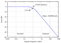
You could start counting the attenuation at zero at the crossover frequency and advance by -6dB per octave, but the response dips a little at the 'knee', being -3dB at said crossover frequency. This image (from Wikipedia - low-pass filter) shows what I mean.
This will be the case only if the driver impedance looks like a resistor (is compensated) or you find an alternative way to extract this response.
Attachments
Last edited:
You are mixing up your m (milli = 10^-3) with u (µ = micro = 10^-6)..............................The tweeter is crossed at ~4k via a 4.7 mF capacitor. (8 ohm) The coil of the larger driver is at 4 ohm impedance. I figure an inductor of ~30-35 mH in series with the coil of the larger driver and the source, (without any capacitor involved) should start attenuating ~2k. At 4k, signal should drop ~12db.
Do I understand this correctly?............
Thanks AllenB, that's the answer I'm looking for.
After I see last pic from wikipedia you uploaded, I'm a litle bit confuse about the meaning of cut off point and crossover point.
What are you guys call for a frequency where the mid and tweeter meet?
When speaker company say their crossover at 4khz, does it mean 4khz is the point where mid & tweeter meet?
Or does it mean that they start the tweeter roll off at 4 khz?
I think (since I am not a Designer) that when we state crossover frequency, we mean the frequency where both drivers give out an equal SPL.Thanks AllenB, that's the answer I'm looking for.
After I see last pic from wikipedia you uploaded, I'm a litle bit confuse about the meaning of cut off point and crossover point.
What are you guys call for a frequency where the mid and tweeter meet?
When speaker company say their crossover at 4khz, does it mean 4khz is the point where mid & tweeter meet?
Or does it mean that they start the tweeter roll off at 4 khz?
For a Butterworth filtered crossover (-3dB relative to passband), the two drivers would be outputting half power @ the crossover frequency. The total power from the two halves would be equal to the passband power of the two individual drivers.
For a Linkwitz Riley filtered crossover (-6dB relative to passband) the phase at crossover is adjusted such that the two quarter power halves add up to an apparent equal SPL as we hear the signal move through the crossover region.
For a single pole crossover, The F-3dB (half power) is given by the traditional F-3dB = 1/2PiRC for the capacitor and F-3dB = R/2PiL for the inductor
on my PC alt+0181 gives µ, but I more often use u instead.I was referring to micro. Ain't got that fancy U on my puter..")
but you have mH and mF and I don't know if these were even intended to be the same multiplier.
According to AllenB's calculation you got them wrong.
Me 'neither..I looked it up and copied it because I forgot the codeI was referring to micro. Ain't got that fancy U on my puter..
u works for me normally.The point is that one inductor is not enough on its own, most of the time. Especially as woofer breakup can sometimes be a little more of a can of worms than something like the tweeter resonance. YMMV.
Erwan, as Andrew says, where they meet. It is most common to have both down by 6dB rather than 3dB. Without measurement it is a tweak away. A second order filter would appear on a graph like the one shown as -6dB at the cut-off.
Thread like this is very helpful for a rookie like me.
I'd like to thank AllenB for these helpful informations.
I'm planning to build my own speaker. 3 way, 4 way, or maybe 3,5 way I havent decide yet.
I dont have any measurement device, and one thing that I worry about is baffle step.
Some people say that .5 driver could overcome the baffle step problem without bsc. But I just dont have any clue about which frequencies the baffle step start to happen.
If there any guidances with this in correlation to the front baffle width or something?
Sorry for the delayed response. Here is a typical example, although each speaker has its own needs.
If a cabinet is 34cm across, then at 1000Hz sound travels half a wavelength to the edge. Out of phase sound is produced by the drop in pressure, as if there were another speaker on the baffle edge. By this time the driver is moving in the opposite direction and they reinforce each other at the listening position, possibly producing a peak. The response might extend an octave below this before falling.
At higher frequencies there will be other peaks and dips. These change the frequency response at different locations, with the delayed version of the direct sound tagging along. Some of this might be audible and rounding the baffle reduces the problem. Changing the baffle shape or the driver position is sometimes used to rearrange the response errors for the listening axis.
At lower frequencies more sound travels behind the baffle where it reflects from the room walls. Baffle step compensation can change the average pressure if it is affected, by simply adding more power. Response issues caused by the reflected energy are more difficult to predict and are usually dealt with by moving the speaker, for example or by making the baffle larger.
The .5 way speaker is just another way to increase the power below some frequency. Its advantage is that the compensation frequency can sometimes be selected with as little as one inductor in series with that driver. This can also work with the .5 on the back of the box, which I think helps to show what's going on.
Oh. I see.
I have read your explanation at the early pages of this thread. You said we could use 3 methods.
I'm interesting with the last method. To build a speaker that doesnt require compensation. But you didnt explain this any further.
If I'm not mistaken, adding .5 driver could be one of them. But sometimes, I hear speaker with .5 driver tend to sound a little dull, slow and boomy in some listening room. Like b&w 603.
Should the .5 driver identical with the woofer? Could we use a bigger driver than the woofer?
Ex: a 3,5 way speaker with 8" woofer as the 3rd driver and 10" for the .5 driver.
At another thread, people say 3 way design could be used to handle this bs issue. Is that right?
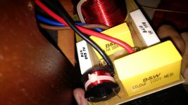
Last night I opened my 2 way b&w 705. And didnt find an additional circuit for bsc. Here I upload the crossover picture. (Crossover point 3,7 khz).
I have read your explanation at the early pages of this thread. You said we could use 3 methods.
I'm interesting with the last method. To build a speaker that doesnt require compensation. But you didnt explain this any further.
If I'm not mistaken, adding .5 driver could be one of them. But sometimes, I hear speaker with .5 driver tend to sound a little dull, slow and boomy in some listening room. Like b&w 603.
Should the .5 driver identical with the woofer? Could we use a bigger driver than the woofer?
Ex: a 3,5 way speaker with 8" woofer as the 3rd driver and 10" for the .5 driver.
At another thread, people say 3 way design could be used to handle this bs issue. Is that right?
Last night I opened my 2 way b&w 705. And didnt find an additional circuit for bsc. Here I upload the crossover picture. (Crossover point 3,7 khz).
Attachments
Ah, I see what you're asking. Let me just point summarise the acoustic change at the baffle frequency as it begins to answer these questions.
Above the baffle frequency:
Hemispherical radiation.
Edge acts as another source of sound.
Below the baffle frequency:
Full spherical radiation.
Wall reflection presents alternative source of sound.
The key to understanding this issue is the change in radiation, for two basic reasons. One is that it changes the set of obstacles that the sound encounters, and apart from special needs for treble versus bass, consistency can be better.. so can avoiding some of the obstacles, each of which can give audible cues to how the sound is being handled.
The other is the ratio of direct to reflected sound because extra power just goes into creating the reverberant (background) field of sound that also has an audible effect.
What the .5 actually does:If I'm not mistaken, adding .5 driver could be one of them.
If you take your speaker outside, when low frequencies wrap around the cabinet the resulting sound is less loud. Put another woofer on the back of the cabinet, it will also wrap but in reverse, so to speak so it will add back the lost sound and the baffle step is fixed.
Since wavelengths are longer, putting the other woofer on the front produces a similar effect.
What it doesn't do:
When you bring this speaker inside, it might create an issue out of the fact that you are using more power for the same direct sound, and expose the rear wall reflection. The result is the same as making a single woofer louder in this band.
This makes it a form of baffle step compensation but not a fix. I should add that successful speakers can be built this way, if the issues are understood. Fixing the baffle step can take the form of either removing it, or simply removing our sensitivity to the issues it creates.
Sure. I base this answer on two things, the fact that people are less sensitive to diffraction in the bass region and it will be primarily the frequency response issues it creates that should be fixed. Secondly, the room (and to some degree the nature of the cabinet edge) will have a greater influence on the response than the woofer itself.Should the .5 driver identical with the woofer? Could we use a bigger driver than the woofer?
This is another form of compensation, not a fix. The benefit of this scheme is putting the baffle step near the lower crossover point to simplify the crossover.At another thread, people say 3 way design could be used to handle this bs issue. Is that right?
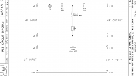
Often a complicated crossover can be simplified. That is to say that a similar filtering impedance might be possible using a different set of components, ie: some could be combined.Last night I opened my 2 way b&w 705. And didnt find an additional circuit for bsc. Here I upload the crossover picture. (Crossover point 3,7 khz).
This is routinely done with, but not limited to, horns. These really aren't that different from flat baffles with regards to waveguiding, which all horns and baffles do. Waveguides are more sensitive to the baffle step than a flat baffle, the step is greater (narrow angle to full-space).I'm interesting with the last method. To build a speaker that doesnt require compensation. But you didnt explain this any further.
Size becomes an issue, just as it would with a flat baffle that is large enough to support all frequencies the driver produces. You can assess the needs at different frequencies and work with this, and thereafter you could also try to control the changes in radiation.
Directivity should be chosen across the spectrum at an early stage of speaker design. The treble is relatively easy. Unless one chooses to create clean 360 degree sound or similar, our sensitivity to diffraction and reflection in the treble means rounding the cabinet and pulling it away from the walls, or by narrowing the radiation pattern with a waveguide or similar.
In the bass, the baffle step can be held off by making the baffle larger, or by placing a large amount of absorbent material behind the speaker so it acts more like it is outside of a room. Fortunately, there comes a point, maybe 200-400Hz, below which the room becomes the primary source of response problems and the baffle you use becomes somewhat irrelevant so you can stop making it larger.
It is the region between this frequency and the baffle step, the lower midrange, that sometimes appears to get overlooked, and can be harder to deal with.
Of the logical options, the most common is to pull the speaker away from the walls, which makes the direct sound stronger relative to reflections. The specific location changes the nature of these room issues to find a workable combination (ie a flat response). This method is based on reducing sensitivity to the issues without undoing the baffle step.
An option that eliminates the baffle step is to use a larger baffle, or to waveguide by narrowing the pattern. This requires a very large speaker at bass frequencies. moving closer to the walls increases the need for a good and well sized speaker until it gets close enough to the walls that it effectively merges, for the frequencies involved, and can then be made smaller. Corner or wall loading speakers has issues to overcome, but benefits as well.
A compromise is to treat the treble well and continue down as low as possible, then let the lower midrange fall as it may and try to clean it up. Dealing with the bass (ie: below the room frequency) is another story, but good bass and treble is a very good place to start.
awesome explanation
Marvelous !!!
What an explanation.
It took me quite some times to understand this without any available pictures, but after I read again, I could understand.
Thank you very much AllenB.
And these bring me some conclusions for the designs that suit my situation
As you said, by making a 3 way design, I could compensate the bs.
So... let's say that I make a 3 or 4 way speaker with 8" woofer and 10"sub. SS-22W and 26W. SS 12MU for mid.
The front baffle would be somewhere between 35 - 37cm width with rounded edges.
At this particular width, aproximatelly, at which frequency the 12MU mid should be crossed with the 22W woofer?
I know it's kinda hard to know an exact point without a measurement. But at least you could give me some estimation numbers or pictures.
If I use all 4 ohm drivers for a 4 way design, would it be problem with the impedance?
I planned to buy the 4rth driver after I collect the money. So, the first project would be a 3 way design. Then add the 10" sub later.
Does it work this way? I mean, could I just add a low pass and high pass circuit in order to make it 4 way without changing the whole circuit?
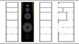
First pic is the baffle plan that I sketch.
Second pic is the b&w 705 detailed circuit. So simple
Marvelous !!!
What an explanation.
It took me quite some times to understand this without any available pictures, but after I read again, I could understand.
Thank you very much AllenB.
And these bring me some conclusions for the designs that suit my situation
As you said, by making a 3 way design, I could compensate the bs.
So... let's say that I make a 3 or 4 way speaker with 8" woofer and 10"sub. SS-22W and 26W. SS 12MU for mid.
The front baffle would be somewhere between 35 - 37cm width with rounded edges.
At this particular width, aproximatelly, at which frequency the 12MU mid should be crossed with the 22W woofer?
I know it's kinda hard to know an exact point without a measurement. But at least you could give me some estimation numbers or pictures.
If I use all 4 ohm drivers for a 4 way design, would it be problem with the impedance?
I planned to buy the 4rth driver after I collect the money. So, the first project would be a 3 way design. Then add the 10" sub later.
Does it work this way? I mean, could I just add a low pass and high pass circuit in order to make it 4 way without changing the whole circuit?
First pic is the baffle plan that I sketch.
Second pic is the b&w 705 detailed circuit. So simple
Attachments
Say that the response levels out above say, 500Hz to 1kHz. To take advantage of this you could put the crossover here so you can treat the high pass driver using a normal high pass filter. You then use a woofer with a slightly higher sensitivity, maybe not the full 6dB (the rest can be made up with attenuation of the mid as required).I know it's kinda hard to know an exact point without a measurement.
The woofer will have a rising axial response that is dealt with using a larger inductor.
I was going to do this once but the frequency involved conflicted with the needs of the speaker I was building so I passed on it. I could have added an extra 'way' but I don't agree with doing this without a good reason.
My point is that it should be a part of the main design, if this is to be used.
- Home
- Loudspeakers
- Multi-Way
- Introduction to designing crossovers without measurement