Feed the Tweeter...
Hi All,
This is my first post on this thread, so let me start by thanking AllenB! This is one of the best and greatest threads on DIYAudio, especially for a beginner like me.
Using information in this thread and some online crossover calculators, I came up with a three-way crossover setup that works very nicely with the speakers I designed using Martin King's computer models. I have included the crossover details below, but my question has to do with the attached pictures.
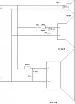
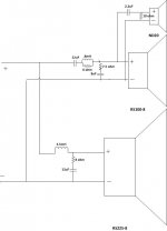
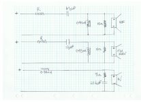
What if any difference would you think there might be by connecting the tweeter the way it is connected in parallel with the other speakers in picture A vs the way it is connected after the mid x-over in picture B?
Thanks in advance!
-----------------Woofer-----------------------------
3.677 mH 600hz Lowpass Filter
Rz 7.93 [ohms] Cz 13.22 [uF] Zobel Network to manage impedance
-----------------Midrange---------------------------
22uF 600hz Highpass Filter - erse
0.8 [mH] Rbsc 6.0 [ohms] Baffel Step Correction circuit Lbsc
Rz 7.562 [ohms] Cz 8.39 [uF] Zobel Network to manage impedance
-----------------Tweeter----------------------------
2.2uF cap in series Highpass Filter
10 Ohm Resister (Flatten the impedance)
Hi All,
This is my first post on this thread, so let me start by thanking AllenB! This is one of the best and greatest threads on DIYAudio, especially for a beginner like me.
Using information in this thread and some online crossover calculators, I came up with a three-way crossover setup that works very nicely with the speakers I designed using Martin King's computer models. I have included the crossover details below, but my question has to do with the attached pictures.
What if any difference would you think there might be by connecting the tweeter the way it is connected in parallel with the other speakers in picture A vs the way it is connected after the mid x-over in picture B?
Thanks in advance!
-----------------Woofer-----------------------------
3.677 mH 600hz Lowpass Filter
Rz 7.93 [ohms] Cz 13.22 [uF] Zobel Network to manage impedance
-----------------Midrange---------------------------
22uF 600hz Highpass Filter - erse
0.8 [mH] Rbsc 6.0 [ohms] Baffel Step Correction circuit Lbsc
Rz 7.562 [ohms] Cz 8.39 [uF] Zobel Network to manage impedance
-----------------Tweeter----------------------------
2.2uF cap in series Highpass Filter
10 Ohm Resister (Flatten the impedance)
Attachments
Last edited:
The capacitor feeding the tweeter is now in series with the resistor across the baffle network, so this capacitor doesm't need to be as large as before. The tweeter will be more quiet due to this resistor.
The mid will be in parallel with the tweeter above the tweeter crossover frequency. Below this the capacitor makes for a higher impedance and the tweeter portion disappears from the circuit.
Up where they are in parallel you'll want to expect your baffle network to become more effective at reducing the level of sound produced (may not be a concern here though.) The mid capacitor should be ok.
Is there something you like about doing it this way?
The capacitor feeding the tweeter is now in series with the resistor across the baffle network, so this capacitor doesm't need to be as large as before. The tweeter will be more quiet due to this resistor.
Does the crossover point change with the capacitor being in series with the resistor?
The mid will be in parallel with the tweeter above the tweeter crossover frequency. Below this the capacitor makes for a higher impedance and the tweeter portion disappears from the circuit.
Will it roll off at a specific rate, say 6db, or does it drop more suddenly (toggle in and out) at a certain impedance? Mid to high is audibly smooth with all kinds of music to my ear and to others who have heard the speakers in this configuration - Maybe I just got lucky!
Up where they are in parallel you'll want to expect your baffle network to become more effective at reducing the level of sound produced (may not be a concern here though.) The mid capacitor should be ok.
Does that mean the BSC is ineffective with the wiring in configuration B?
Is there something you like about doing it this way?
I designed Configuration A with some slightly different component values, but Configuration B just sort of happened as I was tinkering with the system - swapping out parts to suite my auditory taste in a trial and error process.
I built a crossover board for the low and mid and for some reason I put the tweeter crossover parts right onto the tweeter itself and plugged that into the mid when I wired the system. The mid and tweeter are physically close together, so that was convenient. I have included a picture.
I love the way the system ended up sounding in Configuration B, so I am leery about changing it now. I don't currently have any way to measure the system, but I will probably break down and buy a mic and some software - any recommendations?
Thanks! -Glen
Attachments
Yes, for example where the resistor equals the tweeter, the frequency will be halved and the level will go down 6dB.Does the crossover point change with the capacitor being in series with the resistor?
Lowering the impedance by adding other loads doesn't change the response on its own. In this case the mid crossover is working into the tweeter at the same time (the impedance is lowered after the mid crossover). The series components are going to share the available signal with this load so that is how the difference comes about.Will it roll off at a specific rate, say 6db, or does it drop more suddenly (toggle in and out) at a certain impedance?
Will it make a difference? The question is how much.. For starters, with the tweeter in parallel with the mid the impedance at that point would be half that of a single driver. The tweeter is in series with its capacitor which add to its impedance, and that doesn't need to rise too much before the total impedance across the mid is closer to what it is on its own.
The maximum effect will be around the 6dB mark, but only if you have a large series resistance so in practice it will be less.. and it will happen around the region where the mid is being attenuated anyway.
The effect of the mid capacitor is too far away in frequency to be significantly affected. The BSC won't be ineffective, just slightly different in a place where it matters less and could be tweaked back anyway.
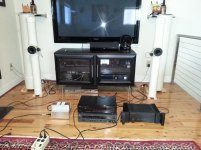
BTW, those are interesting, do you have a front photo of them?
Last edited:
Here's a better picture from the front. I was trying them out with different amplifiers. They sound best with my gainclone.
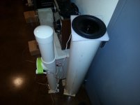
These are older pictures with the first set of stuffed bass pipes I made. The project started out as a 4" full range setup. The first thing I did was add the super tweeter, then the bass pipes came later. After the success I had with the sound of this first small set of bass pipes I messed around in Mathcad some more and came up with really tall stuffed bass pipes that sound thunderous but smooth, and they blend in well with the mid-tweeter setup at all volumes.
The up-firing woofer crossed at 600hz works very well in the pipes. They aren't at all boomy and they have an openness about them. I have tried them in several rooms with different characteristics (live, dead, large, small, etc...) and they always sound great.
I have them in pieces at the moment because I am finishing them, but I hope to have them back together soon.
Thanks for your interest in them!
Attachments
I've used gainclones (using the earlier chip) and found them to be a very good general purpose amp.
I've run dipoles to around 250Hz. These give a spaciousness as well.
The other end of the scale is full baffle control, or even waveguiding with horns. These can give a sound as free of room reflections as headphones if desired, and allow diffraction control that makes them good for use with tweeters, for example. Though i haven't tried waveguides and dipoles at the same time, some have and like it.
There is a school of thought that if you are choosing to include the room in your acoustics, then a speaker that radiates in all directions has a way of doing it well. 600Hz seems a good choice because with a wavelength of almost two feet the woofer should still be spreading the sound. Furthermore this is approximately the point below which we are not as sensitive to diffraction.they have an openness about them.
I've run dipoles to around 250Hz. These give a spaciousness as well.
The other end of the scale is full baffle control, or even waveguiding with horns. These can give a sound as free of room reflections as headphones if desired, and allow diffraction control that makes them good for use with tweeters, for example. Though i haven't tried waveguides and dipoles at the same time, some have and like it.
My gainclone uses the LM3875 chip and it handles these speakers very well. I used the Audiosector boards and borrowed heavily from Peter Daniel's Patek look and design. I love this little amp so much I am building another one to play with.
Of course none of this works without a good crossover, and I think I stumbled onto one. Even with my unconventional wiring! I tried different baffle sizes and shapes using cardboard, but I didn't like the way the speakers sounded with any of them, so I tried the BSC and achieved pleasing results immediately. Without the BSC the speakers have a bright and uncontrolled sound to them. The BSC really smooths things out nicely.
Wave guides interest me and I will likely try them on another design to try controlling room acoustics. You'll appreciate this - Some of the inspiration for my "pipe" project came from an accessory I found during my research by a company called Argent. It's called the RoomLens HemHoltz Resonator. The RoomLens is comprised of three free standing clusters of pipes placed strategically in a room to control the acoustics. My theory was if the RoomLens made a difference in a room, why not use the same principal to design the speaker cabinet itself. And to me, the design is successful. Put the mid-tweeter pipe in front of the bass pipe and the sound melts around the pipes in a very pleasing way before being reflected in the room. SixMoons.com did a review of the RoomLens some time ago, check it out here: 6moons audio reviews: Argent RoomLens HelmHoltz Resonators
My other inspiration was the el pipe-o experiment by Nelson Pass. Check that one out here: https://www.passdiy.com/pdf/el-pipe-o.pdf
My quest for the perfect pipe will be taking me toward a line array configuration for the mid-tweeter pipe once I finish this project. PVC will be perfect for this application since you can simply stack the "T" pipes and glue on the little tweeter pipes.
Last edited:
Yes, at this point I'm inclined to point out the difference in room acoustics above and below the middle hundreds of Hertz.
At low frequencies you have modes related to the room dimensions. The Argent system makes me think of this. There is much that can be done with multiple subs as covered on this site, for example by Gedlee.
Higher frequencies can be seen as having specular (mirror-like) reflections from walls. Controlling these is easier, and usually effective with simple means that deal with the beamwidth.
Line arrays are similar to waveguides. They often control vertical dispersion but you can make an array of drivers in the form of a spherical cap, for example which controls dispersion all around.
Hi Allen
Firstly thanks for the knowledge that you have taken the time to share and present.
I came across this site shortly after commencing a speaker restoration.
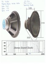
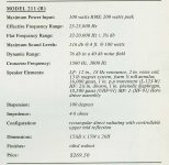
Speakers are Cerwin Vega 211R ( see Spec sheet )
I have conducted the appropriate calculations as per the method presented here which i will post in the next couple days
In the mean time.. was wondering whats your thoughts were on the factory crossover.
Looking at what you have presented here the factory looks a little too basic.
Thanks again
Firstly thanks for the knowledge that you have taken the time to share and present.
I came across this site shortly after commencing a speaker restoration.
Speakers are Cerwin Vega 211R ( see Spec sheet )
I have conducted the appropriate calculations as per the method presented here which i will post in the next couple days
In the mean time.. was wondering whats your thoughts were on the factory crossover.
Looking at what you have presented here the factory looks a little too basic.
Thanks again
Attachments
Hi Allen
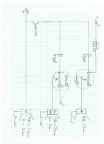
Here is a diagram of crossover i have calculated as per instructions presented here.
Some notes:
All available information i have in relation to speaker impedance and speaker resistances are shown on post #351.
Will start with 10 ohm resistors on the Mid range and tweeter to flatten the impedance
Where you see "R" will utilize the 15 ohm pots
Will use factory crossover settings as shown on speaker spec sheet, 1500 Hz for the woofer looks ideal, unfortunately do not have any graphs for the tweeter and mid horn.
Have dismantled and cleaned pots with 600 grit and applied dielectric grease, they work like new now!
Have also fitted brand new diaphragms to mid horns as the originals were not identical ( 1 read 8 ohms the other 14 ohms)
Woofer and tweeters measured identical.
Not sure if i have the mid horn part right, i applied the calculations as if it were a tweeter.
Any thoughts?
Attachments
Very dumb question!
This is probably a question asked and answered a million times but I can't find a relevant direct answer.
I am using two 8 ohm (nominal) woofers wired in parallel together with one 8 ohm (nominal) tweeter, also wired in parallel for a two-way system. To make the first guess at component values for say a 2nd order L-R low pass and 4th order L-R high pass crossover circuit, what R values should one use in the calculator? Is it best to use half the R (impedance) value from the ZMA curve at the crossover frequency for the woofer (since there are two impedances in parallel), and then the straight R (impedance) value from the ZMA curve for the tweeter also at the desired crossover frequency? Using nominal DC resistance values doesn't seem to make sense. Not halving the woofer impedance also doesn't seem to make sense.
Thanks all for the incredible iformation available on this forum.
Alan
One crossover half filter feeding one 8ohms tweeter needs an 8ohms crossover.
One crossover half filter feeding a parallel pair of 8ohms bass/mid drivers needs a 4ohms crossover.
The amplifier sees a 4ohms to 8ohms load. The output stage needs to be designed to drive 4ohms speakers.
One crossover half filter feeding a parallel pair of 8ohms bass/mid drivers needs a 4ohms crossover.
The amplifier sees a 4ohms to 8ohms load. The output stage needs to be designed to drive 4ohms speakers.
Thanks Andrew - I guess the question is still whether we use the "nominal" 4 and 8 ohm DC resistance values to choose the components via a crossover calculator, or whether it makes more sense to use the values from the .ZMA curves at the crossover frequency - i.e. approx 10 ohms for one driver (Scanspeak 18W8531G00) at 3200Hz, hence 5 ohms for two parallel drivers and then 6.83 ohms for the tweeter (Hiquphon OW1) which is its impedance at the same frequency? Maybe it doesn't matter that much if one is going to do final tuning with a signal generator and oscilloscope but I guess the right choice "up front" helps, doesn't it? Maybe I'm missing something ...
Thanks again Andrew - so it seems ("to be sure to be sure!") that for the woofer and tweeter I have specified, 5 ohms (for the 2 paralllel woofers) and 6.83 ohms are the best choices to get the required starting point for component values for a crossover network.
Of course if one uses a simulator like XSim (Bill Waslo), I presume that to get a correct simulation result, one has to then wire in the two woofers in parallel and load the .frd and .zma data for both.
Thanks again for replying to this dumb set of questions!
Alan
Of course if one uses a simulator like XSim (Bill Waslo), I presume that to get a correct simulation result, one has to then wire in the two woofers in parallel and load the .frd and .zma data for both.
Thanks again for replying to this dumb set of questions!
Alan
First of all thank you very much for the tutorial. Very helpful and informative. The time and effort you have put in to it is much appreciated.
If anyone could clarify a couple of things or correct me if I have got it wrong that would be really helpful")
Looking at the tweeter crossover, if I understand correctly the parallel resistor is used mainly to flatten the response but also has a direct effect of altering the speakers impedance (load at the amp)? This change appears to be corrected in the speaker circuit shown by an addition resistor connected in series. The series resistor can/is also used to alter the output of tweeter. That being said, if the output of the tweeter is already close to the level required, but has a peak in response that needs correcting and already has a low impedance, how do we go about correcting that? Do we look at it as the relationship between with the parallel and series resistor balances out the impedance (if we do the calculation correctly) then we just think of changes to the series resistor value as further attenuation?
Now for the really dumb question...if say the tweeter has a peak at 550Hz, as in the tutorial example, but we are crossing at 2500Hz why do we need to concern ourselves with flattening frequencies which are below our filter point?
If anyone could clarify a couple of things or correct me if I have got it wrong that would be really helpful
Looking at the tweeter crossover, if I understand correctly the parallel resistor is used mainly to flatten the response but also has a direct effect of altering the speakers impedance (load at the amp)? This change appears to be corrected in the speaker circuit shown by an addition resistor connected in series. The series resistor can/is also used to alter the output of tweeter. That being said, if the output of the tweeter is already close to the level required, but has a peak in response that needs correcting and already has a low impedance, how do we go about correcting that? Do we look at it as the relationship between with the parallel and series resistor balances out the impedance (if we do the calculation correctly) then we just think of changes to the series resistor value as further attenuation?
Now for the really dumb question...if say the tweeter has a peak at 550Hz, as in the tutorial example, but we are crossing at 2500Hz why do we need to concern ourselves with flattening frequencies which are below our filter point?
That's fine. You might want a low pass on the mid, I'm not sure. The important issue with a horn system is that you cross the drivers where their directivity matches. This is something that would need measurement to be certain.Not sure if i have the mid horn part right, i applied the calculations as if it were a tweeter.
- Home
- Loudspeakers
- Multi-Way
- Introduction to designing crossovers without measurement