Never had problems by StackingToroid transformers.
Yes, you are right. I was thinking of regular coils as in crossover components.
Can anyone answer my previous question?
Also I connected an SPDif input to the dac and even then it won't display a signal on the output even though the "lock" LED lights up whenever I play a music file.
So at this point the DAC refuses to output a signal via I2S or SPDIF even though it is locking on to it.
Also I connected an SPDif input to the dac and even then it won't display a signal on the output even though the "lock" LED lights up whenever I play a music file.
So at this point the DAC refuses to output a signal via I2S or SPDIF even though it is locking on to it.
Can anyone answer my previous question?
Also I connected an SPDif input to the dac and even then it won't display a signal on the output even though the "lock" LED lights up whenever I play a music file.
So at this point the DAC refuses to output a signal via I2S or SPDIF even though it is locking on to it.
Have you installed the volume pot or a jumper in it's place?
Max input voltage should be 5V, so you will want to lower that. 4.5-4.9V will be a much safer range.
After our latest email exchange, I was planning on sending you a replacement 1.3V Trident.
Unless something happened to the Buffalo, it is working fine.
Adjusted my PS (amb sigma11) to 4.88V and got the 1.3V replacement yesterday.
Hooked everything up and finally got music playing!
Next in line is hooking up the Chronus and getting panels fabricated and FPE.
Thanks for the help Brian!
TPA said:Max input voltage should be 5V, so you will want to lower that. 4.5-4.9V will be a much safer range.
Is that new requirements (lower than 5V) for Trident SR?
Is that new requirements (lower than 5V) for Trident SR?
No, but 5V is a good max voltage with the SR regulators.
Hi,
my BIIIse pro arrived today in Germany
But a part on one 3,3 V Trident is missing/got lost. it is labeled L1.
Think is a ferrite bead? Do someone know part specs?
thx
Branko
Anyone?
Hi,
my BIIIse pro arrived today in Germany
But a part on one 3,3 V Trident is missing/got lost. it is labeled L1.
Think is a ferrite bead? Do someone know part specs?
thx
Branko
That's a pretty strange problem. L1 is a 600-ohm ferrite bead. Without it, you would get no output, so it must have broken off sometime after testing. Bizarre.
I can send you a new Trident.
I'm using the volume pot.
Also for some reason it stopped doing the inverted DC shifting thing when I adjust the volume and it remains @ 1.8v when I adjust the volume now. Something weird is going on.
How are you measuring the voltage of the outputs? I think this measurement is likely a red herring.
Can you check the output voltages of the Tridents and AVCC?
To be clear, it worked fine, then stopped working? What is the input voltage and how are you deriving it?
That's a pretty strange problem. L1 is a 600-ohm ferrite bead. Without it, you would get no output, so it must have broken off sometime after testing. Bizarre.
I can send you a new Trident.
I had the new tridents laying on my working table and some children in the house used them to play with
")
Don't know what happened exactly. The trident seems to be fine otherwise (by eye) and I think I could solder the part on (hopefully). Thank you for your kind offer.
Do you have a part number? will try to get here in Germany.
I had the new tridents laying on my working table and some children in the house used them to play with
Don't know what happened exactly. The trident seems to be fine otherwise (by eye) and I think I could solder the part on (hopefully). Thank you for your kind offer.
Do you have a part number? will try to get here in Germany.
BLM31PG601SN1(BLM31PG601SN1B,BLM31PG601SN1K,BLM31PG601SN1L)|Ferrite Beads/Frequency Specified Filters|EMI Suppression Filters|Noise Suppression Products/EMI Suppression Filters|Murata Manufacturing Co., Ltd.
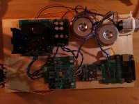
Hey, so I finally got the time to finish a prototype for my Buffalo-IIIsePro38 build.
It took me some time to figure out the exact wiring but in the end I think I got everything right. I configured the Placid HD BP according to the manual and adjusted the correct voltage of 5 volts for the LCPDS. After assuring that the output voltages are correct I powered up everything.
The good news: The relays on the Mercury etc. clicked nicely and apparently nothing blew up! (at least I couldn't see or smell anything)
The bad news: The four LEDs of the Hermes-BBB only flashed for a brief moment and it seems that the BBB is gone now. I am unable to turn it on with its designated power adapter.
Any suggestions how I should proceed? I attached a photograph of my prototype build. Anything obvious that is wrong?
Thanks!
* Hermes-BBB Isolator Module
* Cronus Re-clocking Module with 45.1584/49.152MHz Rhea Pair
* Buffalo-IIIsePro38 2-Channel DAC w/Full Series Regulator Set (Already ordered)
* Mercury I/V Stage (when available)
* Low Current Dual Power Supply HO Kit (For Buffalo and Cronus, suggested by Brian)
* Placid HD 2.1 Bipolar Power Supply Kit (For Mercury, suggested by Brian)
* 9V+9V (30VA) Power Transformer (For LCDPS HO)
* 15V+15V (50VA) Power Transformer (For Placid HD)
It took me some time to figure out the exact wiring but in the end I think I got everything right. I configured the Placid HD BP according to the manual and adjusted the correct voltage of 5 volts for the LCPDS. After assuring that the output voltages are correct I powered up everything.
The good news: The relays on the Mercury etc. clicked nicely and apparently nothing blew up! (at least I couldn't see or smell anything)
The bad news: The four LEDs of the Hermes-BBB only flashed for a brief moment and it seems that the BBB is gone now. I am unable to turn it on with its designated power adapter.
Any suggestions how I should proceed? I attached a photograph of my prototype build. Anything obvious that is wrong?
Thanks!
Attachments
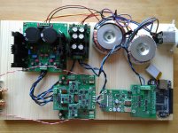
Okay, so much about the correct wiring :-/. So, I will use the "left side" (regarding the photo) of the LCPDS for both the Buffalo and Cronus, use the "right side" for the Hermes. But this shouldn't be the reason for destroying the BBB and the Hermes loosing its power, right?
I provided a daylight photo of the whole setup and of the battery wiring also. I thin I took it from some online documentation. Could this be the reason for blowing up the BBB?
I provided a daylight photo of the whole setup and of the battery wiring also. I thin I took it from some online documentation. Could this be the reason for blowing up the BBB?
Attachments

Okay, so much about the correct wiring :-/. So, I will use the "left side" (regarding the photo) of the LCPDS for both the Buffalo and Cronus, use the "right side" for the Hermes. But this shouldn't be the reason for destroying the BBB and the Hermes loosing its power, right?
Surely not, but it could have a significant role in reduced sound quality or even ground loops
I provided a daylight photo of the whole setup and of the battery wiring also. I thin I took it from some online documentation. Could this be the reason for blowing up the BBB?
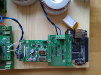
I think there is a misunderstanding about the small external battery used to avoid BBB damage in shut down.
I see in the pics that the two square 4-pins connectors (male and female) that should connect hermes to BBB external battery pads (near the barrel psu connector) are not soldered, so the protective action from the small ext battery did not take place. More, the battery has not to be connected the way you did: the ext_bat connector has a different purpose, for what i can understand.
Without protective action from external battery, BBB has to be switched off using the specific button onboard, otherwise it can be seriously damaged. Did you always switch it off using the onboard button?
Last edited:
Surely not, but it could have a significant role in reduced sound quality or even ground loops
Okay. That's what I have expected.
I think there is a misunderstanding about the small external battery used to avoid BBB damage in shut down.
I see in the pics that the two square 4-pins connectors (male and female) that should connect hermes to BBB external battery pads (near the barrel psu connector) are not soldered, so the protective action from the small ext battery did not take place. More, the battery has not to be connected the way you did: the ext_bat connector has a different purpose, for what i can understand.
Without protective action from external battery, BBB has to be switched off using the specific button onboard, otherwise it can be seriously damaged. Did you always switch it off using the onboard button?
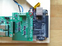
You mean the four 2x2 connectors I circled with red? Where do I have to connect the external battery then?
So far I always powered the BBB with its dedicated power supply. This was the first time it was connected to the Hermes and the damage obviously occurred when I turned on the Hermes for the first time (as I said the Hermes LED's turned on for a brief moment and went out again).
Attachments
- Home
- More Vendors...
- Twisted Pear
- Introducing the Buffalo III-SE-Pro 9028/9038