We had fun and got a lot of very positive feedback on our products at the NY Audio Show. Thanks to a couple of diyaudio readers who came.
We sold out of our Classic Phono Stage but expect to have more by the end of the week (~ Nov. 13). Because a number of people who wanted to buy the Classic Phono Stage at the show discount couldn’t because we were sold out, we’re extending it until Nov. 20. And we’re making the 10% discount available to anyone on our website using the code NYASCLASSIC10. The discount applies to boards and kits as well as assembled units. Obviously, it's no good on assembled units until we actually make a few more, but soon...
Scott
The Classic Phono Preamp is now back in stock, both assembled and kit versions. We got a nice mention in stereophile for our room at the NY Audio Show.
The New York Audio Show: Saturday Part Two | Stereophile.com
Scott
The New York Audio Show: Saturday Part Two | Stereophile.com
Scott
Thats great your show went well Scott. Do you have any photos?
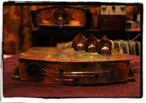
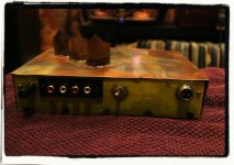
I finally finished my Classic.
Made a few errors along the way, Scott was great in helping me sort them out. These boards are very high quality. Considering the amount of times I desoldered stuff trouble shooting.
I have mine just running MC, but MM works fine. Only using a Ortofon Rondo blue at the moment.
The Classic is a brilliant phono stage, dead quiet, does what it suppose to do very well. (Im not good at reviewing, but its the best phono stage Ive heard so far)
Would recommend any body wanting to DIY to at least buy the parts kit as well. Save a bit of hassle getting the correct parts.
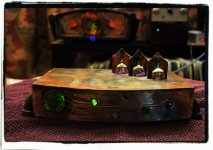
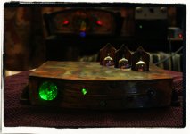
I made the box from copper and wood. Looks nice to me at night time.
Many thanks again Scott.
I finally finished my Classic.
Made a few errors along the way, Scott was great in helping me sort them out. These boards are very high quality. Considering the amount of times I desoldered stuff trouble shooting.
I have mine just running MC, but MM works fine. Only using a Ortofon Rondo blue at the moment.
The Classic is a brilliant phono stage, dead quiet, does what it suppose to do very well. (Im not good at reviewing, but its the best phono stage Ive heard so far)
Would recommend any body wanting to DIY to at least buy the parts kit as well. Save a bit of hassle getting the correct parts.
I made the box from copper and wood. Looks nice to me at night time.
Many thanks again Scott.
Attachments
Is there a kit available for your Adagio phono stage?
Thank you,
Mas
Hi Mas,
Thanks for asking.
Not yet. I had not originally considered the Adagio as a possible kit, but a number of people have asked, and I'm definitely considering it.
It would be a fairly advanced kit, with a lot of hand wiring off the PCBs. And writing an assembly manual for it as detailed as I prepared for the Classic would be a big investment in time.
I have another kit in the product queue, then I'll turn some attention to an Adagio kit.
Thanks,
Scott
Thats great your show went well Scott. Do you have any photos?
Hi Paul,
Thanks for the kind words. I'll post some photos from the show on our website soon.
Scott
Hi Scott,
I was wondering, what the input and output impedance is on the 6SL7 Phono Stage?
--Dave
Hi Dave,
Output impedance is < 1000 ohms. Input impedance on the MM input is 47.5 kohms, with adjustable capacitance from ~35pF to ~ 360pF.
Input impedance on the MC input is adjustable from 71 ohms to 47.5 kohms.
Details on the exact values are covered in the owner's manual, which is already online. This is a new product and will be available as an assembled unit or kit in a few days. My son will also be picking our next raffle winner soon - odds of winning are pretty high (much better than powerball).
Thanks,
Scott
Vintage 6SL7 Phono Stage (MM / MC) – Tavish Design
Hi Everyone,
Our new Vintage 6SL7 Phono Stage is now available, as an assembled product, a kit, or a blank circuit board. As with our previous kit, the Assembly and Setup Manual (which includes schematics, parts lists, measurements, photographs, etc.) is a free download, even if you don’t buy anything.
We’ve also created “export kits” for both the Classic Phono and Vintage 6SL7 Phono. These kits omit a couple of heavy components and are less impractical to ship outside North America.
As always, let us know if you have any questions.
Scott
Agggggggggghhhhhh!!!!!adjustable capacitance from ~35pF to ~ 360pF.

Yes, I thought you'd figure it out, sorry to be elliptical. There's about 130-140pF of input capacitance before you add any caps or cables. The input tube is undegenerated, so gain is about 50 or so. 2.8pF plate to grid, 3pF grid to cathode, so assuming a best case of zero strays, Cin = 50*2.8 + 3.
Yes, I thought you'd figure it out, sorry to be elliptical. There's about 130-140pF of input capacitance before you add any caps or cables. The input tube is undegenerated, so gain is about 50 or so. 2.8pF plate to grid, 3pF grid to cathode, so assuming a best case of zero strays, Cin = 50*2.8 + 3.
35pF is a measured value at 1 kHz. It is tricky to measure accurately, so it could be higher, yes. But the calculation of Miller capacitance is more complicated than that, since the tube loading is a function of frequency, due to the passive EQ. Gain decreases from 20Hz to 500Hz as the effective load on the first tube plate decreases. I simulated ~ 70pF at 1kHz, and I'm not sure why the measured value is lower, but I generally trust measurement over simulation.
So, the effective input capacitance is a function of frequency. It is one of the disadvantages of these very simple passive circuits. But keep in mind that load capacitance on the cartridge only matters at high frequencies, where is resonates with the cartridge inductance. And beyond 1kHz or so, it is much more constant.
If you're still convinced I'm wrong, I'll measure it again. But of course, it is still small w.r.t. the cable capacitance.
Scott
You've got an 82k build-out resistor, so that limits the gain reduction in the first stage to asymptotically 35 or so. I didn't calculate the 1k value, but that's the limit as the capacitive reactances go to zero- most of the concern is in the 10k-20k range anyway.
How are you measuring the input C? There's some tricks which I'm guessing you know...
How are you measuring the input C? There's some tricks which I'm guessing you know...
You've got an 82k build-out resistor, so that limits the gain reduction in the first stage to asymptotically 35 or so. I didn't calculate the 1k value, but that's the limit as the capacitive reactances go to zero- most of the concern is in the 10k-20k range anyway.
How are you measuring the input C? There's some tricks which I'm guessing you know...
The hand-calculated HF gain to the plate of the first stage is about 33, yes. So based on the published Cgp of the 6SL7GT, you might expect about 92pF of Miller cap, and I simulated 70pF. But I think it is suspicious that the 6SL7GT Cgp is always stated as 2.8pF, regardless of the manufacturer, or freq, or structure of the tube. I wonder who measured that 2.8pF, and when? Somebody at RCA in 1941, I suspect.........
I measured the input cap by applying a signal from a sine wave generator thru a large series R, at a variety of frequencies, up to 20kHz. (With and without the amp connected, and with and without the input tube.) Then measuring the input amplitude and calculating the effective input Z vs Freq. It is tricky because the capacitor is insignificant compared to he 47kohm input R until the frequencies get high. I'll measure it again to be sure. It'll be a few days.
Scott
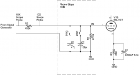
The phono stage input capacitance question turned out to have an interesting answer. Since my capacitance meter won’t accurately measure capacitance in this range with a shunt 47k ohm resistor, I set up a test jig as shown in the attached figure. I used a 432k ohm resistor in series with my signal generator to apply a signal to the phono stage at various frequencies up to 20 kHz. By measuring the signal amplitude on each side of the 432k ohm resistor, the input impedance of the phono stage can be calculated as a function of frequency. From this, the input capacitance can be calculated.
This measurement is subject to errors due to the small signal levels, but it occurred to me that I could use the 47pF and 100pF load capacitors on the board to calibrate the measurement. The phono stage board capacitance was first measured without the tubes, but with either the 47pF or 100pF load capacitor turned on. Then the phono stage board capacitance was measured with the tubes in place and operating, but without the added load caps.
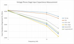
The results are shown in the second figure. When the capacitance of the test jig (about 25pF, mostly due to scope probes and the 8” twisted pair to the input of the phono stage) is subtracted off, the minimum input capacitance is about 85pF with Sovtek 6H9C/6SL7GT tubes and 74pF with Tung Sol Reissue 6SL7GT tubes. These numbers include about 8pF of stray capacitance on the PCB.
I’ll update the Vintage Phono Stage input capacitance specs in the Owner’s Manual and Assembly Guide.
Scott
This measurement is subject to errors due to the small signal levels, but it occurred to me that I could use the 47pF and 100pF load capacitors on the board to calibrate the measurement. The phono stage board capacitance was first measured without the tubes, but with either the 47pF or 100pF load capacitor turned on. Then the phono stage board capacitance was measured with the tubes in place and operating, but without the added load caps.
The results are shown in the second figure. When the capacitance of the test jig (about 25pF, mostly due to scope probes and the 8” twisted pair to the input of the phono stage) is subtracted off, the minimum input capacitance is about 85pF with Sovtek 6H9C/6SL7GT tubes and 74pF with Tung Sol Reissue 6SL7GT tubes. These numbers include about 8pF of stray capacitance on the PCB.
I’ll update the Vintage Phono Stage input capacitance specs in the Owner’s Manual and Assembly Guide.
Scott
Attachments

Hi everyone,
We’ve picked our latest diyaudio raffle winner, for either a Classic Phono Stage PCB or Vintage 6SL7 Phono Stage PCB (including free shipping). The winner has been notified by PM.
The raffle winner is chosen randomly from all those who post a question, suggestion, or constructive comment on Tavish Design’s vendor thread(s). Odds of winning are pretty high.
We plan to hold at least one more raffle. Those who did not win this time are reentered for next time. Winners can only win once.
Best,
Scott
Vintage 6SL7 Phono Stage (MM / MC) – Tavish Design
Nothing to add here other than great work! I know how difficult owning a small business is - especially in niche products. Clearly your measurements and genuine interest speak for itself. When Im in the market for a phono again, I'll surely be heading your direction (plus you're not too far away!)
Keep up the good work,
Steve
Keep up the good work,
Steve
- Status
- This old topic is closed. If you want to reopen this topic, contact a moderator using the "Report Post" button.
- Home
- Vendor's Bazaar
- Introducing Tavish Design