I was refering to Zenmod's answer to where the two CL-60 hookup.....he said to the same spot....I didnt know if they should be seperate or not, your info about 2 star grounds has me thinking, but Master ZenMod says they should go to same spot, sounds like you've come to same conclusion. Now I feel better about putting mine in.......for about a year now I've listened to this sucker without the CL-60s and power cords alligator clipped into position. What a lazy *** I am!Yeah, I answered it. I'm pretty confident 2 CL-60s go to one point on the chassis.
russellc


Well, the problem just went from bad to worse.
There are wild swings on DC output. Anywhere from -7v to +7v or more.
It won't stay put. On starting the amp cold across R12 it reads .29v and 7.xV.
With lid on, it warms up after 1.5 or 2 hours and the reading goes to .50+ and .250mV.
DC doesn't come down very fast. It takes the full 2 hours. This could be bad on speakers to have that much DC, correct?
This circuit doesn't use protection or thermal circuit. Maybe it's time to put it in?
.....Maybe it's time to put it in?
nope
first you must solve that berserk issue of your amps
give us pictures
Guess what I learned today? Lifting the PCB ground will make adjustment impossible.
I put the PCB grounds back at 0V on the PS. The output DC is stable now. The bias is stable too. I set it to .40 and will let it warm up.
Later I'll change the crappy RCAs.
Will update later.
Thanks,
Vince
I put the PCB grounds back at 0V on the PS. The output DC is stable now. The bias is stable too. I set it to .40 and will let it warm up.
Later I'll change the crappy RCAs.
Will update later.
Thanks,
Vince
Attachments

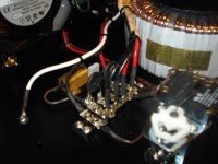
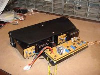
Lead dressing, and grounding
Although I'm relatively new to Class A audio, my DIY experience in scratch-building linear RF amps (tube and solid-state) really taught me lessons about lead dressing and proper grounding. I'd agree--some of your construction may be leading to your current problems. Best of luck. It's always tougher to run down a problem in a chassis that's "kinda messy".
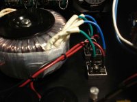
Here's part of my F5 build, FYI. Yeah. It took a little time, but consider it an investment.
Although I'm relatively new to Class A audio, my DIY experience in scratch-building linear RF amps (tube and solid-state) really taught me lessons about lead dressing and proper grounding. I'd agree--some of your construction may be leading to your current problems. Best of luck. It's always tougher to run down a problem in a chassis that's "kinda messy".
Here's part of my F5 build, FYI. Yeah. It took a little time, but consider it an investment.
Attachments

You guys are probably sick of me by now, but there's another development.
I stopped by Radio Shack and picked up a $17 ground loop isolator. I was hoping it would work and it actually does work...well. The sound did not degrade, in fact there is some extra bit of resolution due to a more quite background.
I'd rather not use it and use better cables, but it is a mental life saver.
Will also try to lift one shield as suggested earlier.
thanks,
Vince
its just a transformer in those breakers though right? surely theres a better way. you know that though, sounds like a thorough and utter debugging is in order, easy to just sit back once you have a working solution, but i know for myself i would have a niggling feeling in the back of my mind that it could be better.
but i know for myself i would have a niggling feeling in the back of my mind that it could be better.
Believe me it bugs me, but the next audio group meeting is at my house on April 10th.
There is so much to do to get ready. At this point, I have to live with the minor buzz in the speakers. It's just bad timing.
We had the March meeting yesterday and one of the guys is a very smart audio engineer. He bought a boat load of Jensen transformers from a studio. He said that these transofrmers are used in the big Neve mixers. I'd rather have nothing in the path, but this has to be better than the loud buzzing and humming! It will have to do.
When this meeting is over, I will take apart the F5 and rewire it.
As a foot note: My friend at yesterdays meeting has my first F5. Traded it with him for some rather hi-end speaker parts. A potential new member has been in the audio sales business for 40 years out of Philly, then Denver. He just ordered a Pass Labs INT-30. He said he hopes his INT-30 sounds as sweet as that F5. Let me tell you what a great feeling it was to hear that, but all the credit goes to Nelson, I said.
Hi Tauro0221,
Are the cathcode or antode connected together without the thermistors? Is this safe?connect them using two diode back to back to earth ground
Hi,
The cathode of one diode is tie to the anode of the other diode. In other word the two should be tie with the anode and the cathode together. This is save because diodes when conducting the voltage across the diodes would be only .5 volts to ground. This is better than the CL60. The CL60 should be use to delay the voltage between the rectifier and the capacitors. I had the same problem with my LM3886. When connecting the earth ground to chassis and the PS ground it is start the humming. I read this method in this web side so I decide to it try and it is worked. Some recommended also a capacitor across the diodes. Just try it as a test.
The cathode of one diode is tie to the anode of the other diode. In other word the two should be tie with the anode and the cathode together. This is save because diodes when conducting the voltage across the diodes would be only .5 volts to ground. This is better than the CL60. The CL60 should be use to delay the voltage between the rectifier and the capacitors. I had the same problem with my LM3886. When connecting the earth ground to chassis and the PS ground it is start the humming. I read this method in this web side so I decide to it try and it is worked. Some recommended also a capacitor across the diodes. Just try it as a test.
- Status
- This old topic is closed. If you want to reopen this topic, contact a moderator using the "Report Post" button.
- Home
- Amplifiers
- Pass Labs
- Interesting Hum Problem - Active 2-Way