I still have a few left overs so if anyone is interested let me know")
I am very interrested in 2, and have the chips already!
Nik
Just had another look at your board design. I understand that the low frequency performance of this regulator is very much dependant upon the value of C Byp, see attached graph (courtesy Hifiduino).
http://hifiduino.files.wordpress.com/2014/02/adm7150by.jpg
In your next iteration, it might be a good idea to allow space/terms for say a 1000uF electrolytic in parallel with the ceramic and the tantalum?
I know the Datasheet recommends solid tantalum but to get up to these kind of values would consume a lot of space (needing multiples) and also would be very expensive?
In application i have no complains so far. I don't know about this article but I will give it a look when i find some free time.
Nik
The graph is straight out of the datasheet and shows noise performance at different frequencies dependant upon the size of the C Bypass value. You will see from the graph that the high frequency performance is pretty independant of the value used but a high value makes a big difference in the low frequency peformance.
Having checked the Datasheet, the absolute maximum rating Bypass to ground is +6V so there should be a few solid tantalum capacitors available at say 1000uF at a reasonable cost for this voltage rating.
I think I will try this value in this position.
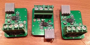
I have built two of these boards now. One of them is a ADM7150 with a fixed output of 3.3V and using a 100uF tantalum bypass capacitor. The other is a variable voltage version with a Rref of 10k and a 25k pot. The bypass capacitor in this one is a 1000uF, 6.3V tantalum. I am using the fixed 3.3V version for the Digital supplies for my ES9018 DAC and the variable one set at 3.8V for the Avcc.
My impression is that these are better than the TPA7S4700 regulators that they replaced. The improvement is subtle (like most power supply improvements are), not a big tonal change that might occur with say swapping opamps in the IV stage. I think the biggest difference is in the bass performance. This might be due to the very large bypass capacitor bringing low frequency noise to very low levels.
Unfortunately, I haven't got suitable measuring equipment to verify all this but I am hoping that other people with the right equipment will do the measurements.
Many thanks for the boards Nik.
Usage questions
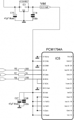
I was planning to use mine to replace a LF33ABDT in Doede's PCM1794 dac that is supplying vdd. The LF33 is setup up with 47uF lytic by passed by a 100nF film caps at its input and at its output. Should I leave those caps in place and just change the regs? Or should I remove any of the caps, at the input or output?
The lytics are nichicons, if I keep them I will replace the output lytic with an oscon most likely (it goes straight to the vdd pin of the dac chip).
Thanks.
@themystical thanks for the response, I'm very happy you like the reg
@palmito Funny, I am thinking about trying Doede's dac with the reg boards too! The only thing holding me back is the price.
I have almost zero experience with PCM1794 so I am not sure. I would say that, what caps you are going to use depends on the reg, on the dac IC and the distance between the two.
My boards follow AD's recommendations for best measurable performance so if the dac is properly decoupled I would suggest to try with no extra caps. Then if you would like to play with them, I would suggest to try different caps on the reg board.
Cheers!
I was planning to use mine to replace a LF33ABDT in Doede's PCM1794 dac that is supplying vdd. The LF33 is setup up with 47uF lytic by passed by a 100nF film caps at its input and at its output. Should I leave those caps in place and just change the regs? Or should I remove any of the caps, at the input or output?
The lytics are nichicons, if I keep them I will replace the output lytic with an oscon most likely (it goes straight to the vdd pin of the dac chip).
Thanks.
As Nik says it is dependent upon your set up. In my case I have 820uF electrolytics at the input of the DAC board the regs are feeding with the reg directly attached to the board very close to this capacitor and this does not seem to upset the regs in any way that I can make out. Nothing is getting warm/hot and Ii don't see any signs of oscillation. It seems to me that the ADM7150/7151 is happy with a large electrolytic on its output.
Mind you, I can't measure this and have not looked at the output of the reg with a scope so YMMV
Thanks Nikitas and themystical. I only have one board and provided my own regs, so it wasn't that expensive, but it's not cheap either!@palmito Funny, I am thinking about trying Doede's dac with the reg boards too! The only thing holding me back is the price.
I have almost zero experience with PCM1794 so I am not sure. I would say that, what caps you are going to use depends on the reg, on the dac IC and the distance between the two.
My boards follow AD's recommendations for best measurable performance so if the dac is properly decoupled I would suggest to try with no extra caps. Then if you would like to play with them, I would suggest to try different caps on the reg board!
I've attached a portion of the schematic for one board. I was originally thinking of removing c13/c14 but keeping c27/c28, but changing c27 to the same value oscon. But I will remove both sets of caps and put just the reg and see how it sounds. I'll report what I find!
Attachments
Last edited:
Thanks Nikitas and themystical. I only have one board and provided my own regs, so it wasn't that expensive, but it's not cheap either!
I've attached a portion of the schematic for one board. I was originally thinking of removing c13/c14 but keeping c27/c28, but changing c27 to the same value oscon. But I will remove both sets of caps and put just the reg and see how it sounds. I'll report what I find!
I wouldn't remove C14 and C28 as they are decoupling capacitors at the pins of the IC's. I think you will find that the datasheet specifies these to be used to keep RF out of the chips and keep things stable. Personally I wouldn't remove the 47uF ones either unless there were some stability issues with your reg.
There is interest for boards for the TPS7a4700 regulator from TI, which can be used for higher voltages.
Here is the datasheet: http://www.ti.com/lit/ds/symlink/tps7a4700.pdf
Is anyone else interested?
Here is the datasheet: http://www.ti.com/lit/ds/symlink/tps7a4700.pdf
Is anyone else interested?
should i solder through the board under the ADM7151?
Yep, definitely!
- Status
- This old topic is closed. If you want to reopen this topic, contact a moderator using the "Report Post" button.
- Home
- Amplifiers
- Power Supplies
- Interested in ADM7151 regulator?